


9 SONIC EXCITER SX3040 User Manual
3.3 Basic operation
Due to the small number of SX3040 controls, this is an easy processor to operate.
Perform the following steps:
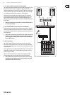
1) Connect the unit according to the application as described in section 3.2.
◊ First make the following settings for one channel (channel 1 or 2
depending on input assignment). For stereo applications choose the
same settings for the second channel.
2) Switch on all devices (amplier and loudspeaker last) and ensure that the
IN/OUT switch (7) on the SX3040 is illuminated, i.e. that the unit is working
and all controls are set to “MIN”. For series connection set the MIX controls to
the middle positions; for parallel connection set them to “MAX” (see sections
3.2.1 and 3.2.2).
3) Turn the DRIVE co ntrol (1) until the desired bass saturation eect is
achieved and the green LED regularly lights up when peak levels occur.
4) Turn the TUNE co ntrol (2) to specify the frequency range for processing.
5) Turn the HARMONICS con trol (5) until the desired enhancement eect in
the high-frequency range is achieved.
6) Turn the TUNE contro l (4) to specify the frequency range for processing.
7) To compare the original and processed signals, repeatedly press the IN/OUT
button. Then adjust the dry/wet balance as desired.
8) Repeat steps 3) to 7) until you are satised with the result.
4. Installation
4.1 Rack mounting
The BEHRINGER SONIC EXCITER SX3040 requires 1 U of height for installation
in a 19-inch rack. Please make sure that you leave around 10 cm for the rear
connections. For installation of the unit in a rack please use M6 machine screws
and nuts.
4.2 Audio connections
There are various ways to integrate the SX3040 into your setup. Depending on
the application you will need dierent connecting cables, and these will be
discussed in the following section.
4.2.1 Cabling with jack cables
To operate the SX3040 in series with other equipment, you will need standard
commercial ¼" jack cables, often referred to as instrument cables or patch cables.
These cables have a ¼" TS jack plug at each end. Connect the inputs of the
equipment with the corresponding outputs of each of the other devices.
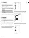
strain relief clamp
sleeve
tip
sleeve
(ground/shield)
Unbalanced ¼" TS connector
tip
(signal)
Fig. 4.1: Unbalanced jack cable with ¼" TS jack plugs
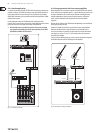
If your other equipment has balanced inputs, use a balanced switched cable
with two stereo jack plugs at the balanced outputs of the SX3040. These cables
provide a high level of security against interference signals such as noise
interference from power cables, and should be used for all long cable routes.
strain relief clamp
sleeve
ring
tip
sleeve
ground/shield
For connection of balanced and unbalanced plugs,
ring and sleeve have to be bridged at the stereo plug.
Balanced ¼" TRS connector
ring
cold (-ve)
tip
hot (+ve)
Fig. 4.2: Balanced jack cable with ¼" TRS jack plugs
Alternatively, you can use professional XLR cables with an XLR socket on one side
and an XLR plug on the other side. This cable connection is the most reliable both
electrically and mechanically.
output
For unbalanced use, pin 1 and pin 3
have to be bridged
1 = ground/shield
2 = hot (+ve)
3 = cold (-ve)
input
12
3
1
2
3
Balanced use with XLR connectors
Fig. 4.3: Balanced XLR plug