


6 EUROPOWER EP4000/EP2000 User Manual
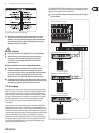
2.2 Rear panel
(10)(9) (16) (15)
(7) (8) (11) (12) (13) (14)
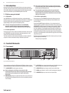
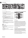
Fig. 2.2: Rear panel control elements
(7) These are the balanced XLR inputs (channels 1 and 2).
(8) These are the stereo ¼" TRS inputs (channels 1 and 2). They can also be used
with unbalanced plugs.
(9) These are the MODE switches, used to alter the operating modes as well as
to set the limiters and high-pass lters (see chapter 2.3).
(10) The unit’s fan is located here. Fan speed adjusts automatically to assure
trouble-free operation.
◊ To prevent faulty operation, please assure that the unit is kept at a
distance from other appliances emanating heat.
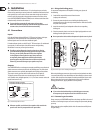
(11) These are the SPEAKER OUTPUTS (channels 1 and 2). When running the
unit in mono-bridged mode (see chapter 2.3.5), please use the channel 1
output exclusively. For further information on the connectors please refer to
chapter4.1.
(12) These are the OUTPUT TERMINALS (channels 1 and 2). When running
in mono, please make sure to use both middle connectors to connect
yourloudspeaker.
(13) BREAKER (automated fuse). After eliminating the cause of faulty operation,
simply depress the BREAKER and power up the unit again. The BREAKER acts
in place of common discardable fuses.
Caution
◊ Before engaging the BREAKER switch, you should power down the unit
(POWER switch set to OFF)!
(14) POWER is supplied via an IEC connector. The matching cable is provided
with the unit.
(15) SERIAL NUMBER of your EUROPOWER.
(16) Here you can nd a detailed overview of the individual MODE SWITCHES
functions (9)).
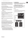
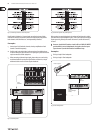
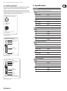
2.3 Conguration switches (MODE SWITCHES)
Fig. 2.3: Dip-switches
2.3.1 Clip limiter
When the input signal connected to your amp is too high, you end up with a
distorted output signal. To prevent this, both channels of your EUROPOWER
feature a clip limiter that can be engaged or disengaged selectively. The limiters
automatically recognize distortion and lower amplication until distortion is
reduced to a tolerable level. To preserve the dynamic characteristics of the signal
when low distortion levels are occurring, the clip limiters function with moderate
suppression. Use switches 1 (ch. 1) and 10 (ch. 2) to activate the clip limiters.
When using broadband loudspeaker systems, the clip limiter reduces high
frequency distortions which occur when an amplier is overloaded. The drivers
are thus protected from being damaged.
2.3.2 Input lter
The LF (high-pass) lter removes frequencies below 30 and 50Hz respectively.
The reproduction of the signal’s bass portion is thus optimized, since ultra-low,
distracting frequencies are eliminated, and more power is available for the
reproduction of the wanted segment of the signal. Engaging and disengaging
the lters is done by using the switches 3 (ch. 1) and 8 (ch. 2). Switches 2 (ch. 1)
and 9 (ch. 2) determine the cut-o frequency. As long as the lter is disengaged,
frequencies below 5 Hz are cut to prevent damage.
You should set up the lters so they best suit the frequency response of your
speakers, since some speakers (e.g. bass reex speakers) are particularly sensitive
to over-excursion below the listed frequency range.