


EUROPOWER EP1500/EP2500
Control elements6
Control elements2.
Since control elements of both the EP1500 and the EP2500 are identical, we have used the EP1500 as the model represented in the
illustrations to assure simplicity.
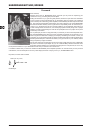
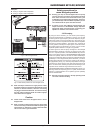
Front panel2.1
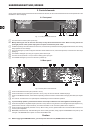
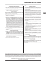
Front panel control elementsFig. 2.1:
The main switch is used to power up the amp.{1}
Merely switching the unit off does not mean that it is fully disconnected from the mains. When not using the unit for +
prolonged periods of time, please unplug the unit’s power cord from the power outlet.
Ventilation openings are located at the front of the unit, so that hot air is prevented from being trapped inside the unit, thus causing {2}
faulty operation or even damage.
The CLIP LED lights up when the signal is distorted. Should distortion occur, reduce the input level, so that the CLIP LED stops {3}
lighting up.
The SIGNAL LED lights up as long as a signal is present at the input.{4}
The Gain control (channels 1 and 2) is used for setting up the input gain.{5}
The POWER LED lights up as soon as the unit is powered up.{6}
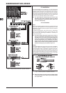
Rear panel2.2
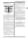
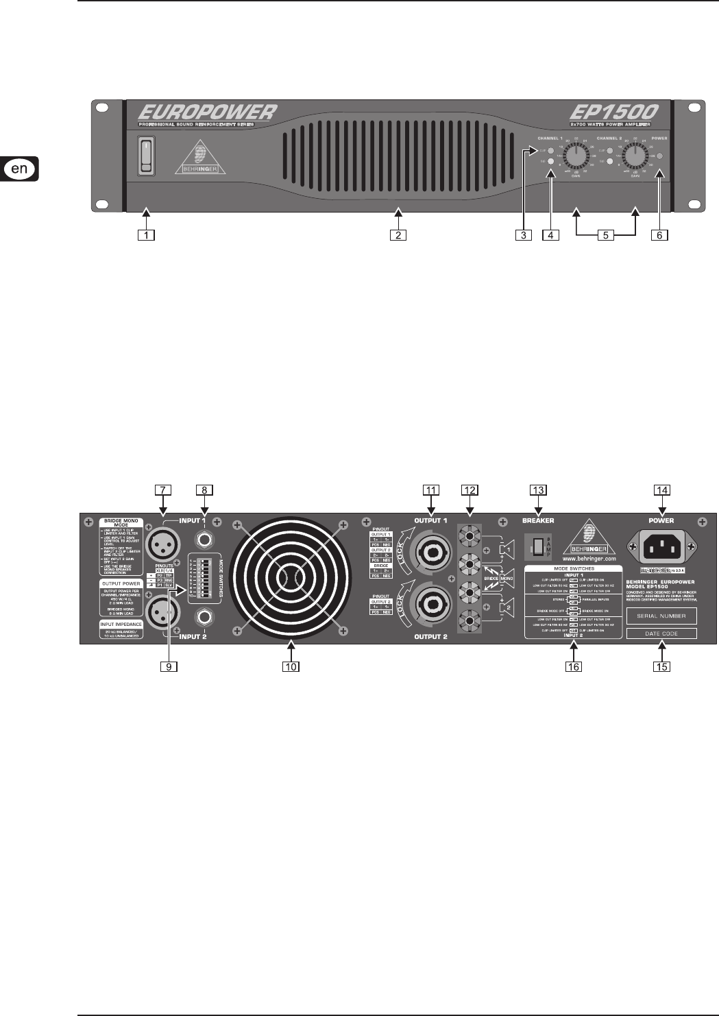
Rear panel control elementsFig. 2.2:
These are the balanced XLR inputs (channels 1 and 2).{7}
These are the stereo 1/4" TRS inputs (channels 1 and 2). They can also be used with unbalanced plugs.{8}
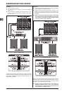
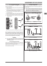
These are the MODE switches, used to alter the operating modes as well as to set the limiters and high-pass lters (see chapter {9}
2.3).
The unit’s fan is located here. Fan speed adjusts automatically to assure trouble-free operation.[10]
To prevent faulty operation, please assure that the unit is kept at a distance from other appliances emanating heat. +
These are the Speakon-compatible outputs (channels 1 and 2). When running the unit in mono-bridged mode (see chapter 2.3.5), [11]
please use the channel 1 output exclusively. For further information on the connectors please refer to chapter 4.1.
These are the output terminals (channels 1 and 2). When running in mono, please make sure to use both middle connectors to [12]
connect your loudspeaker.
BREAKER (automated fuse). After eliminating the cause of faulty operation, simply depress the BREAKER and power up the [13]
unit again. The BREAKER acts in place of common discardable fuses.
Caution
Before engaging the BREAKER switch, you should power down the unit (POWER switch set to OFF)! +