EUROPOWER EP1500/EP2500
Installation 11
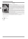
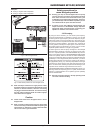
Using the binding posts4.1.1
To connect the loudspeakers to the amplier’s binding posts,
please do the following:
Switch off the amp and disconnect it from the mains (unplug 1.
mains connector).
Remove the protective plastic covers shielding the binding 2.
posts by loosening the two screws on the right-hand side of
the connections and lift the plastic cover upwards.
Attach the terminal of your loudspeaker cable to the corres-3.
ponding binding post.
Place the protective plastic covers into its original upright 4.
position on each binding post and replace the two screws.
Never operate the device without the protective plastic +
covers in place!
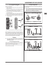
Protective plastic covers shielding the binding postsFig. 4.2:
When using binding post connectors, please make sure that insu-
lation on cables is not removed too high. Insert the naked part of
the cable fully so that no metal is visible. Cable clamps must be
isolated to avoid the possibility of electric shock. When running the
amp in mono-bridged mode, always use the middle two binding
post connectors, paying attention to correct polarity.
Caution
If you notice naked cable endings on the binding post +
connectors, do not power up the amp because of the
risk of electric shock.
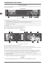
Connecting to the mains4.1.2
Always connect your EUROPOWER amplier to the voltage speci-
ed on the rear of the device. Connecting the amp to an incorrect
voltage can permanently damage your amp.
Before powering up the amplier, double-check all connections
and fully lower the gain setting.
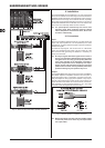
Audio connections4.2
Various cables are needed for different types of applications.
The following illustrations show the correct wiring. Always use
high-grade cables.
When connecting a balanced input signal, please make +
sure to exclusively use balanced cables for passing the
signal further on. Otherwise, one single unbalanced
cable can turn the entire signal unbalanced.
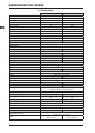
XLR connectionsFig. 4.3:
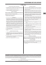
1/4" TS connectorFig. 4.4:
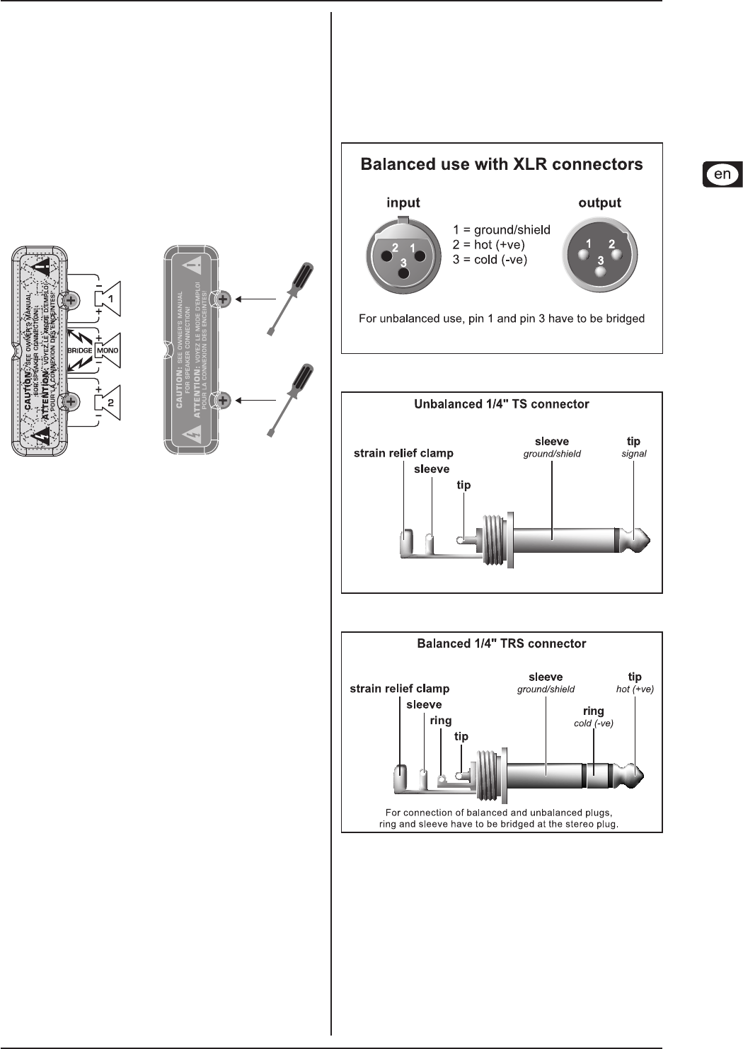
1/4" TRS connectorFig. 4.5: