


EUROLIVE E1220A/E1520A
Control elements and connections 5
Initial operation1.1.2
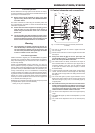
Be sure that there is enough space around the unit for cooling.
To avoid overheating, do not place the E1220A/E1520A on top of
power amps or near radiators, etc.
Blown fuses must be replaced by fuses of the same +
type and rating. Please refer to the “SPECIFICATIONS”
for further details.
The mains connection is made using the enclosed power cord
and a standard IEC receptacle. It meets all international safety
certication requirements.
Please make sure that all equipment is properly ground- +
ed at all times. For your own safety, never remove or
disable the ground conductor of the unit or of the AC
power cord.
The sound quality may diminish within the range of pow- +
erful broadcasting stations and high-frequency sources.
Increase the distance between the transmitter and the
device and use shielded cables for all connections.
Warning
This loudspeaker is capable of producing extreme vol- +
umes. Please keep in mind that high sound pressures do
not only temporarily damage your sense of hearing, but
can also cause permanent hearing damage. Be careful
to select a suitable volume at all times.
Online registration1.1.3
Please remember to register your new BEHRINGER equipment
right after your purchase by visiting www.behringer.com (alterna-
tively www.behringer.de) and read the terms and conditions of
our warranty carefully.
Should your BEHRINGER product malfunction, our goal is to
have it repaired as quickly as possible. To arrange for warranty
service, please contact the retailer from whom the equipment was
purchased. Should your BEHRINGER dealer not be located in your
vicinity, contact directly one of our subsidiaries. Corresponding
contact information is included in the original equipment packag-
ing (Global Contact Information/European Contact Information).
Should your country not be listed, please contact the distributor
nearest you. A list of distributors can be found in the support area
of our website (www.behringer.com).
Registering your purchase and equipment with us helps us process
your repair claims quicker and more efciently.
Thank you for your cooperation!
Control elements and connections2.
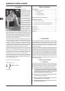
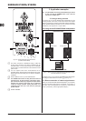
Control elements and connections (E1220A and Fig. 2.1:
E1520A)
Use this 1/4" stereo jack to connect a signal source that {1}
has 1/4" output.
Use this XLR connector to connect a signal source that has {2}
XLR output.
Always use either the XLR or the 1/4" jack input, and +
use the LEVEL control {4} to adapt the input sensitivity.
Never use both inputs at the same time!
The {3} LINK OUTPUT is directly connected to the inputs of
the E1220A/E1520A and carries the input signal with no
processing applied. In this way, you can route the signal
to the input of another device (for example, a second
E1220A/E1520A).
To set the volume of the LINE or MIC signal, use the {4} LEVEL
control. The left half of the control range is for attenuating
the LINE signal. The right half is for raising the level of the
MIC signal.
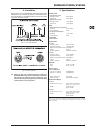
The {5} CLIP LED lights up when signal distortion occurs.
Reduce the volume with the LEVEL control until the CLIP
LED does not light up any more, or occasionally lights up
at signal peaks.
We would like to draw your attention to the fact that ex- +
tremely loud sound levels may damage your hearing as
well as your headphones/loudspeakers. Turn the LEVEL
control fully to the left before you switch on the unit. Be
careful to select a suitable volume at all times.
The {6} HIGH control adjusts the level of the high-frequency
range.
The {7} PWR LED lights up when the loudspeaker is put into
operation.
The {8} LOW control adjusts the level of the low-frequency
range.