


7 ULTRA-DI PRO DI800 User Manual
the original equipment packaging (Global Contact Information/
European Contact Information). Should your country not be listed,
please contact the distributor nearest you. A list of distributors can be
found in the support area of our website (http://behringer.com).
Registering your purchase and equipment with us helps us process
your repair claims more quickly and eciently.
Thank you for your cooperation!
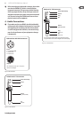
2. Control Elements
The BEHRINGERULTRA-DI PRO features eight identically built
channels. The control elements described here refer therefore to
all channels.
(1) The INPUT connector is used for connecting unbalanced as well
as balanced signal sources.
(2) Because both INPUT and LINK connectors are wired in parallel,
the LINK TRS connector can be used both as an input and
as a direct unbalanced output of the INPUT signal. For the
latter, you can for example connect LINK with the input of a
monitor amplier.
(3) The unbalanced input signal can be tapped into at the UNBAL
OUT TRS connector – after passing through the amplication
circuitry (see
(4) and (6) ). Essentially, the signal is identical
to the signal located at the XLR output in the back; the only
dierence is that it is unbalanced and has therefore no Ground
Lift functionality (see
(5) ).
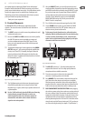
(2) (4) (6)
(7)(5)(3)(1)
Fig. 2.1: Front panel control elements
(4) The -30 dB attenuation switch increases the operating range
of the DI800 considerably, from low signal levels of a high-
impedance mic or a guitar, all the way to speaker connectors of
a guitar amplier.
◊ Use the -30 dB switch only when the DI800 starts distorting
(and not the mic preamp). When this is not the case,
avoid using this function, since the lowest amount of
attenuation is desirable in order to obtain the lowest
signal-to-noise ratio possible.
(5) Using the GND LIFT switch, you can fully separate input and
output grounding. Depending on how the equipment to which
your DI800 is connected is grounded, using the GND LIFT switch
lets you lower hum noise or ground loops. When the GND LIFT
switch is depressed, the ground connection is interrupted
(the LED is lit red). When the switch is in the PHANTOM OR
MAINS POWER ON setting, the LED is lit green (when the
GND LIFT switch is not pressed).
(6) The +20 dB switch increases the input signal level by 20 dB.
(7) Use the POWER switch to power up your DI800. The POWER
switch should always be in the “O” position when you are
about to connect your unit to the mains.
◊ To disconnect the unit from the mains, pull out the mains
cord plug. When installing the product, ensure that the plug
is easily accessible. If mounting in a rack, ensure that the
mains can be easily disconnected by a plug or by an all-pole
disconnect switch on or near the rack.
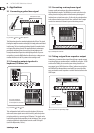
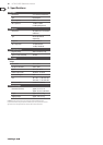
(11) (10)
(9) (8)
Fig. 2.2: Rear panel connectors
(8) The BAL OUT connectors (1 - 8) are the balanced mic-level
outputs of the channels 1 to 8. Use a high-quality balanced
microphone cable to establish connection.
(9) The mains connection is achieved via the standard IEC
connector. A matching power cord is included.
(10) Serial NUMBER. The serial number is located on the top of the
unit. Please take a few minutes and send to us a completely
lled out warranty card within 14 days of the original date of
purchase. Otherwise, warranty claims may be rendered invalid.
Or ll out the warranty information online at behringer.com.
(11) FUSE COMPARTMENT/VOLTAGE SELECTION: Before plugging
the unit into a power socket, please make sure you have selected
the correct voltage. Faulty fuses must be replaced with fuses of
appropriate rating without exception. Some units feature a fuse
compartment that can be operated in two dierent positions,
allowing alternating between 230 V and 120 V. Attention: when
using the unit outside of Europe (running on 120 V), you have to
use a fuse with a higher rating (see chapter 5 “Specications”).