


12
B-CONTROL FADER BCF2000/B-CONTROL ROTARY BCR2000
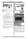
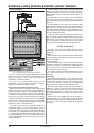
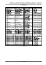
Stand Alone-Mode S-3:
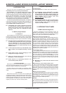
Fig. 4.8: Routing and use in stand-alone mode 3
In this mode, MIDI data from the BCF2000/BCR2000 is mixed
with the data coming in at the MIDI input (merge function), but is
exported exclusively on output A. Only control data of the
B-CONTROL is available at output B.
This way, you can control two MIDI devices from your
B-CONTROL, but only the device connected at OUT A can
additionally be played from the MIDI keyboard.
Important information about stand-alone modes:
When connecting this way, parameter values of the controlled
devices can be shown by the LEDs of your B-CONTROL. If
parameter feedback is important, connect MIDI IN to MIDI OUT
of the device you want to control. Of course, the hardware has to
be capable of sending a response about the current parameter
values. If you are not sure, check the equipments user manual.
Parameter feedback in stand-alone mode 3 functions when MIDI
output B is used. In all other stand-alone modes, undesired MIDI
loops can occur; control data of the B-CONTROL are transmitted
via MIDI OUT B only in stand-alone mode 3.
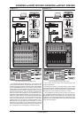
If you want to daisy-chain two B-CONTROLs to jointly control
several MIDI devices, you need to connect OUT A of the first
B-CONTROL to MIDI IN of the second B-CONTROL. OUT A of
the second B-CONTROL needs to be connected to the MIDI input
of the effects unit. If additional MIDI devices need to be talked
to, please connect the THRU port of one MIDI device to the IN
port of the next MIDI device. This way, with different MIDI channel
assignments, each MIDI device can be controlled from each one
of the B-CONTROLs.
If additional MIDI inputs are needed, then external MIDI merge
boxes must be used. For example, if your sound module only has
one MIDI IN connector, and you want to control if from several
MIDI controllers and from a keyboard, you will need a 2-in/1-out
merge box.
If additional MIDI outputs are required, you will need external
thru boxes. With more complex MIDI setups, thru boxes are
preferred to using longer thru chains to prevent data transmission
problems.
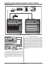
Your B-CONTROL can also control your computer via MIDI
(without a USB connection) as long as your computer features a
MIDI interface. In this case, all stand-alone modes can be used.
When using parameter feedback, you must use stand-alone mode 3,
and should connect your computer via MIDI IN and MIDI OUT B,
so that no feedback loop occurs.
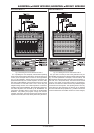
If you dont require the response function during software control,
you can connect as many BCF2000/BCR2000s as you want per
MIDI. The last B-CONTROL in the chain is then connected to the
MIDI IN input of your computer. This way, you can control nearly
as many channels of a software mixer as you wish. However,
keep in mind that all devices must share 16 MIDI channels.
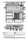
4.2 Play mode menu
The Play mode menu is the highest menu level in the
B-CONTROL. Use it during normal operation for real-time control
of MIDI data.
Display:
After switching on the unit, the current system software version
is briefly displayed. Value changes are shown when using one of
the control elements.
Control elements:
You can use several keys, encoders and faders simultaneously
and send their MIDI data. The classification of MIDI data types is
explained in chapter 4.3. According to its assigned MIDI data
type, each control element shows the current parameter value in
the corresponding LED or LED ring.
The position of the faders changes automatically as soon as
you choose another preset or during incoming parameter
messages.
LED display:
The encoder LED ring displays or the status LEDs of the
buttons change automatically when running controller recordings
in a sequencer, provided, of course, all connections have been
made correctly, the correct operating mode is enabled and the
software sequencer supports sending parameter values.
Button illumination varies according to the controller mode: if a
button is in Toggle on mode, the button LED illuminates as
soon as the button is pressed. Only when you press the button
once again, the LED goes out. If a button is in Toggle off mode,
the corresponding LED will be lit only for the time the button is
pressed.
The LED rings of the encoders are normally displayed in a
multi-step manner, i.e. turning the encoder from left to right lights
the first LED followed by the next, whereby the first LED goes out
etc. This way, even small value changes can be displayed
accurately.
4. CONTROLS