


en
Control elements
6
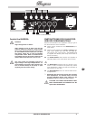
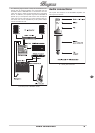
Rear panel
CAUTION!
!
Hot! Risk of injury! During use, the valves
get very hot and high surface temperatures
may be reached at the rear of this unit.
Avoid touching the controls and connectors
on the rear panel during use. To avoid acci-
dental contact with hot surfaces, place the
rear panel so that it faces a wall.
The 18 SEND output is used to connect a shielded ¼"
mono jack cable to the input of an external effects
unit.
The 19 RETURN input is used to connect a shielded
¼" mono jack cable to the output of an external
effects unit.
The 20 PREAMP OUT SEND output takes the preamp
signal of the amp in order to feed the signal to a
second amplier and loudspeaker combination, for
example.
The 7-pin 21 FOOTSW(itch) connector is provided to
connect to the supplied BUGERA FSB104A foot-
switch. Please be sure to connect the cables before
switching on the amplier. Refer to „Footswitch“ for
details.
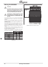
The 22 IMPEDANCE switch lets you specify the loud-
speaker impedance. Always apply the value that
is identical to the impedance of the used speaker
cabinet. When connecting two cabinets with the
same impedance, the switch should be set to half
the value of one of the cabinets. For example, two
16-Ohm cabinets would require an 8-Ohm setting,
while two 8-Ohm cabinets need to be set to the
minimum impedance of 4 Ohms. Please also read
„Wiring the BUGERA“.
!
Both the paralleled 23 LOUDSPEAKER outputs (¼"
mono jacks) are used to connect the speaker
cabinet(s). The minimum impedance is 4 Ohms. The
IMPEDANCE switch should always be set to match
the impedance of the used speaker cabinet.
ATTENTION! TO AVOID DAMAGE TO YOUR
!
AMP, NEVER USE THE BUGERA VALVE AM-
PLIFIER WITHOUT A LOUDSPEAKER CON-
NECTED!
*
WARNING: ONLY REPLACE THE FUSE WHEN THE 24
MAINS CABLE HAS BEEN DISCONNECTED! The
FUSE is found in the fuse holder. If the fuse is
blown, it needs to be replaced with a fuse of the
same kind by all means. Otherwise, the unit could
seriously be damaged, in which case the warranty
is void. If the fuse is blown repeatedly, you should
take the unit to a qualied service technician.
*
The 25 IEC MAINS connector is used to connect the
mains cable that has the appropriate voltage rat-
ings for your country (included). At all times, make
the connections to the amplier before plugging the
cable into a power outlet.
This is the 26 SERIAL NUMBER of the amplier.
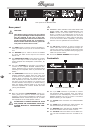
Footswitch
Footswitch BUGERA FSB104A
The 7-pin 27 DIN connector is provided to connect
the footswitch cable (included). Then, the cable is
connected to the FOOTSW(itch) connector of the
BUGERA amplier. Be sure to make a connection
before switching on the amplier.
The 28 CLEAN switch activates the CLEAN/CRUNCH
channel.
The 29 LEAD switch activates the LEAD channel. Its
LED illuminates when the channel is active.
The 30 REVERB switch activates the REVERB effect.
Its LED illuminates when the effect is active.
The 31 FX LOOP switch activates the FX LOOP func-
tion. Its LED illuminates when the FX LOOP is ac-
tive.
Rear panel of the BUGERA 6260