


English
Owner’s manual
Dear Customer,
Thank you for choosing B&W. Please read this manual
fully before unpacking and installing the product. It will
help you to optimise its performance. B&W maintains
a network of dedicated distributors in over 60 countries
who will be able to help you should you have any
problems your dealer cannot resolve.
Environmental Information
All B&W products are designed to comply
with international directives on the
Restriction of Hazardous Substances
(RoHS) in electrical and electronic equipment and the
disposal of Waste Electrical and Electronic Equipment
(WEEE). These symbols indicate compliance and that
the products must be appropriately recycled or
processed in accordance with these directives. Consult
your local waste disposal authority for guidance.
Carton Contents
Check in the carton for:
1 Foam plug
1 Accessory pack containing:
4 M6 spike feet
4 Rubber feet
4 Lock nuts (10mm across flats)
Speaker Installation
The speakers are intended to be floor mounted only. It
is important to ensure that the speakers stand firmly
on the floor using the spike feet supplied whenever
possible. The spike feet are designed to pierce carpet
and rest on the floor surface. Initially, screw the lock
nuts onto the spikes enough to leave the nuts floating
just above the carpet when the spikes are resting on
the floor beneath. Screw the spikes fully into the
threaded inserts in the base of the cabinet. If the
cabinet rocks when placed on the floor, unscrew the
two spikes that do not touch the floor until the cabinet
rests firmly without rocking. Finally, lock the nuts
against the cabinet. It may be more convenient to fit
and adjust the spike feet after speaker positioning has
been optimised.
If there is no carpet and you wish to avoid scratching
the floor surface, use either a protective metal disc (a
coin perhaps) between the spike and the floor, or use
the supplied rubber feet. Fit the rubber feet and level
the cabinet in the same manner as with the spike feet.
Speaker Positioning
Adjustment of speaker position following initial
installation will probably further improve the sound
quality and is usually worthwhile.
In either stereo or home theatre installations, try to
ensure that the immediate surroundings of each
speaker are similar in acoustic character. For example,
if one speaker is adjacent to bare walls while the other
is adjacent to soft furnishings and curtains, both the
overall sound quality and the stereo image are likely to
be compromised.
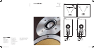
Conventional Stereo Systems
To begin with, the speakers should be positioned
between 1.5m and 3m apart at two corners of an
equilateral triangle completed by the listening area at
the third corner. The speakers should be
approximately 0.5m away from the back wall, and at
least 0.5m away from any side walls. Figure 1a
illustrates this arrangement.
Home Theatre Systems
If the speakers are to be used for the front channels in
a home theatre system, they should be placed closer
together than for 2-channel audio, because the
surround channels tend to widen the image.
Positioning the speakers within approximately 0.5m of
the sides of the screen will also help keep the sound
image in scale with the visual image. As with
conventional stereo positioning, the speakers should
ideally be approximately 0.5m away from the back
wall, and at least 0.5m away from any side walls.
Stray Magnetic Fields
The speaker drive units create stray magnetic fields
that extend beyond the boundaries of the cabinet. We
recommend you keep magnetically sensitive articles
(CRT television and computer screens, computer
discs, audio and video tapes, swipe cards and the
like) at least 0.5m from the speaker. LCD and plasma
screens are not affected by magnetic fields.
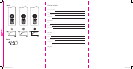
Connections
All connections should be made with the equipment
switched off.
There are 2 linked pairs of terminals on the back of the
speaker. For conventional connection, the terminal
links should remain in place (as delivered) and just one
pair of terminals connected to the amplifier. For bi-wire
connection, the terminal links should be removed and
each pair of terminals connected to the amplifier
independently. Bi-wiring can improve the resolution of
low-level detail. Figures 2a and 2b illustrate
conventional and bi-wire connection.
Ensure that the positive terminals on the speaker
(marked + and coloured red) are connected to the
positive output terminal on the amplifier and the
negative terminals on the speaker (marked – and
coloured black) are connected to the negative output
terminal on the amplifier. Incorrect connection can
result in poor imaging and loss of bass.
Ask your dealer for advice when selecting speaker
cable. Keep its total impedance below the maximum
recommended in the speaker specification and use a
low inductance cable to avoid attenuation of high
frequencies.
Fine Tuning
Before fine tuning, make sure that all the connections
in the installation are correct and secure.
Moving the speakers further from the walls will
generally reduce the volume of bass. Space behind
2
6965 CM7 OM Inside iss5.qxd 9/4/08 11:36 Page 2