


CAUTION
RISK OF ELECTRIC SHOCK
DO NOT OPEN
�
1000-WATT ACTIVE
FULL-RANGE SYSTEM
ACT-1515X
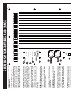
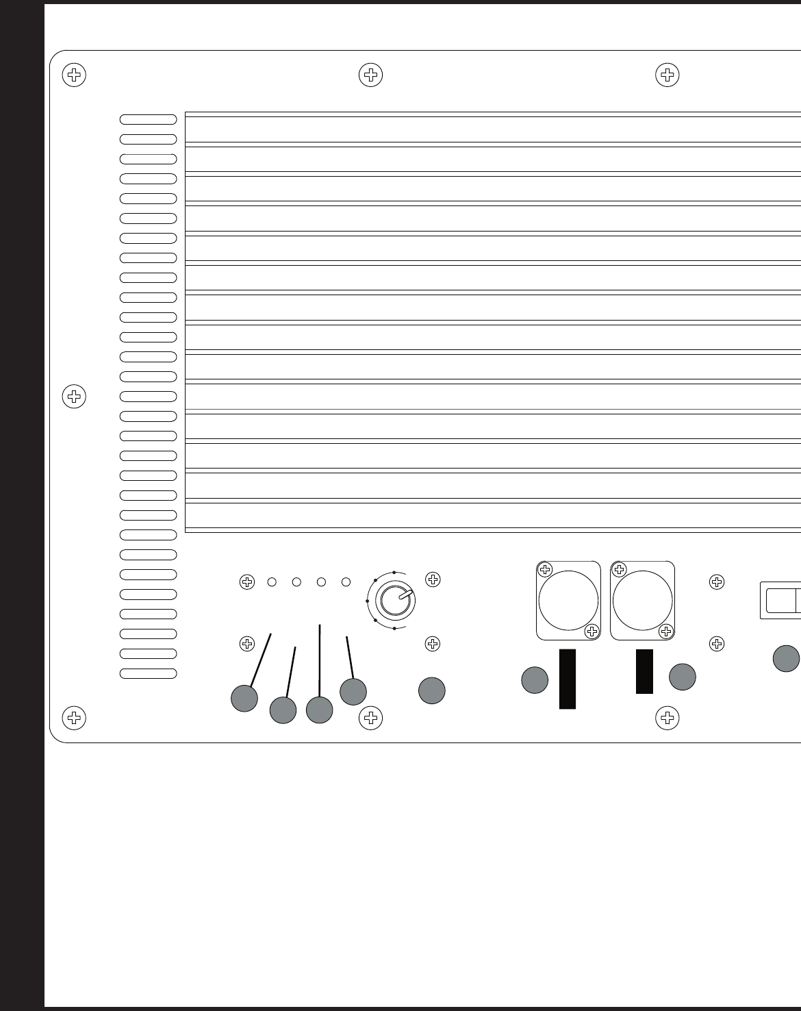
SPEAKER SYSTEM FEATURES AND USAGE
NUMBERS IN THIS SECTION REFER TO THE NUMBERED
CONTROLS OPPOSITE
1) POWER INDICATOR: This LED indicates that the amp
is powered on normally, and should be capable of producing an
audio signal in concert with the attached speakers. If this light
and the signal light (#4) are both lit, yet no sound is present,
there is a fault condition, possibly blown loudspeakers. If this
light is on but the signal light (#4) is un-lit, this indicates that
there is no signal present at the input of the amplifier, or the
amplifier input section is damaged.
2) PROTECT: This Amber LED turns on when there is a fault
condition in the system causing circuitry to engage in order to
protect the amplifier and prevent it from damaging itself and/or
the attached speaker(s). The most common cause of this is run-
ning the amplifier at or near its maximum output level for a
very long time. If protection is engaged because of overheating,
the best course of action is to turn down the level control on the
amplifier for long enough (10-15 minutes) to allow it to cool
off. After this time if the amp no longer turns on, it should be
turned off for 10 seconds and then turned on again. If it still
does not operate, contact your authorized service provider or
B-52 Pro-Audio.
3) LIMIT: This LED indicates the signal input is high enough
to drive the amplifier into compression. Compression is the
artful limiting of the signal volume at the input stages, to prevent
the otherwise gross distortions that result from driving the power
amplification beyond its design limits.
4) SIGNAL: This LED indicates the presence of audio at the
input stage of the amplifier. If this light is not lit the sound will be
very low or nonexistant.
5) LEVEL CONTROL:
Sets the volume of the ACT-1515X(F)
without influencing the level at the output XLR send.
6) OUTPUT:
This connector is shorted to the INPUT allowing
daisy chaining of the input signal. Therefore you do not need
to y-cable out of your mixer or audio device to get an addi
-
tional full range signal(s) to another active system nearby your
ACT-1515X(F) speaker system. Use this connector to “daisy
chain” multiple systems together. (See diagram on page 6 for
details)
7) INPUTS: This XLR connector accepts a balanced input
signal cable. Balanced means the signal is referred to a ground
whose voltage is always centered between the voltage present
on pins 2 and 3. The wiring conforms to the Audio Engineering
Society standard where Pin 2 is (+) or hot; Pin 3 is (-) or cold; and
Pin 1 is the Shield or ground.
8) EARTH GROUND: DO NOT DEFEAT THE EARTH GROUND
IF AN ELECTRICAL STORM IS IMMINENT!! Use the feature only
with great caution. Defeating the Earth ground may in some
instances reduce or eliminate hum due to unavoidable ground
loops. It also disconnects the amplifier panel from the third
prong of the AC cable. That prong will lessen the chance of lethal
voltages being present on the amplifier panel should there be
a lightning strike or other catastrophic failure on the AC mains
power line. Lifting the Earth ground means a person in contact
with the amplifier panel in such an event has a greater likelyhood
of dying in the event of such a catastrophic fault. DO NOT LIFT
THE EARTH GROUND UNLESS YOU CAN ASSURE NO ONE WILL
COME INTO CONTACT WITH THE AMPLIFIER PANEL DURING USE.
9) POWER ON/OFF SWITCH: Turns on the AC mains
power and your ACT-1515X(F) amplifier. If power is available
and the amp is working properly, the Power ON/OFF switch will
light up. If it does not, unplug the AC cable from the wall and
then check the AC mains fuse in your ACT-1515X(F) for conti
-
nuity with a multimeter or ohmmeter. If the fuse is open (no
continuity) replace with same kind and type. If the replace-
ment fuse blows in short order, seek service from a qualified
technician.
10) POWER CORD CONNECTOR:
For attachment of
the included IEC standard detachable power cord. Please replace
this cord should it become chafed, cut, bent or damaged in such a
way that the protective insulation is compromised.
TOUCHING LIVE EXPOSED WIRES ON THE POWER CORD CAN
RESULT IN INJURY OR DEATH! Only replace the cable with the
exact same type and size.
11) FUSE HOLDER:
House a 8 amp (115 Volts) or 4
amp (230 Volts) 3AB size slow-blow fuse. REPLACE ONLY WITH
SAME KIND !!!! NOTE!!! Very often a blown fuse is a symp
-
tom of a serious problem with the amplifier or speaker. Under
normal operating conditions the fuse should NEVER go open.
It does so only under fault conditions. Take extreme care with
household electricity as it has the potential for deadly harm. Do not
expose the amplifier inside by removing the amp from the
cabinet and then plugging it into AC mains power. Voltages present
on the printed circuit board can be lethal! If the fuse repeatedly
blows, especially on first powering up the amp, it is an indicator
of a fault condition and the AC mains power should be removed
and the entire system should be brought into a qualified service
technician for repair. VOLTAGES PRESENT ON THE PRINTED
CIRCUIT BOARD WHILE THE AMP HAS AC MAINS POWER SUPPLIED
TO IT ARE POTENTIALLY LETHAL !!