


page 4 page 5
Using an APS VR module and VHF Transmitter(s)...
The APS VR receiver module comes pre-adjusted to one of 30 dif-
ferent VHF frequencies between 169MHz and 213MHz. The particular
frequency(s) you have were chosen to not interact/interfere with TV sta-
tions in your area. After installing the module (page 2) you will have to
attach the antenna and position it as close to vertical as possible. The
volume control on the module adjusts the input volume of that particular
module. Try to keep it set near its mid point for best performance.
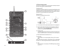
Transmitters...
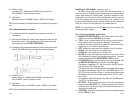
Model 31LT: Lavalier microphone with body-pack transmitter. Ideal for speaking
applications such as Lecturers, Actors, Actresses, etc.
(1) Open the battery compartment lid by sliding it down and raising it.
(2) Insert one fresh Alkaline 9-volt battery into the compartment. Make sure the
battery polarity is correct.
(3) Frequency Label
The Frequency label indicates what frequency (in MHz) the transmitter broad
casts on. The AZDEN receiver in use must also be on the same frequency.
(4) 31LT lavalier mic:
Clips onto a tie, lapel, etc. The transmitter’s cable doubles as an antenna.
Extend the cable as much as possible for the best performance.
(5) Audio Input Level Control
Turn clockwise to increase, or counter-clockwise to decrease the input level.
A small screwdriver is supplied to make adjustments. The level control is
factory-preset in the center position.
7. LINE IN - this mono RCA jack is designed to accept audio from
devices such as CD players, video tape players or anything else with
a line-level audio output. The input volume is controlled by the LINE
LEVEL knob (6).
8. LINE OUT - this mono RCA jack provides line-level audio to drive
additional speakers or other audio devices with a line-level input.
The level is controlled by the MASTER VOLUME CONTROL (A) on
the front panel. If this output is used to drive the LINE IN (7) of a
second APS 25, the MASTER VOLUME CONTROL (A) will control
the overall volume of both speakers.
9. AC JACK - this is where the removable AC plug is attached to the
speaker. The AC plug is polarized and will only attach one way.
10. AC FUSE - the replaceable AC fuse is housed here. Follow the mark-
ing on the panel for proper replacement if needed (0.5A for 210-
240VAC use or 1.0A for 110-125VAC use).
11. AC VOLTAGE SELECTOR - set down when used with 110-125VAC
(US and other areas) and up when used with 210-240VAC (Europe
and other areas). Be sure to check your local voltage before adjust-
ing the selector. The speaker is shipped from the factory set in the
110-125VAC position and with a cable designed for that voltage.
Mounting the APS 25
• Wall Mounting
(see photo - page 9)
The APS 25 is supplied with a wall mounting bracket. It can be at-
tached to the speaker via the built-in 1/4
" X 20 threaded holes on the top
and bottom of the speaker using the included large screws. Supplied
rubber pads can be applied to the inside surface of the bracket to protect
the speaker surface from scratching and reduce the possibility of the
speaker rotating in the bracket. The bracket can be attached to the de-
sired surface using a number of different fasteners. Be sure to use fasten-
ers that are appropriate for the surface you are mounting to and that can
support the speaker’s weight. Once the desired position is achieved, tighten
the screws securely.
• Stand Mounting
The APS 25 has two industry-standard 5/8" x 27 threaded inserts moul-
ded into the cabinet - one on the bottom and one on the side. These allow
the speaker to be securely mounted to a stand (such as a microphone
stand). Be sure to tighten the speaker securely to the stand. Also, be sure
that the stand can support the weight of the speaker and that it will be
stable with that weight attached.
• Flat surface
Four self-adhesive anti-skid pads can be applied to the bottom or side
of the speaker to help stop it from moving when placed on a flat surface.