


page 3page 6
(6) 3-Position Switch
Left position:OFF - Middle position:STANDBY - Right position:ON
In the “STANDBY” position, the audio is muted.
(7) LED Indicator
RED when switch is in “STANDBY” position - GREEN in “ON” position.
NOTE: Remove the battery if the transmitter will not be used for a long period of
time.
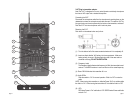
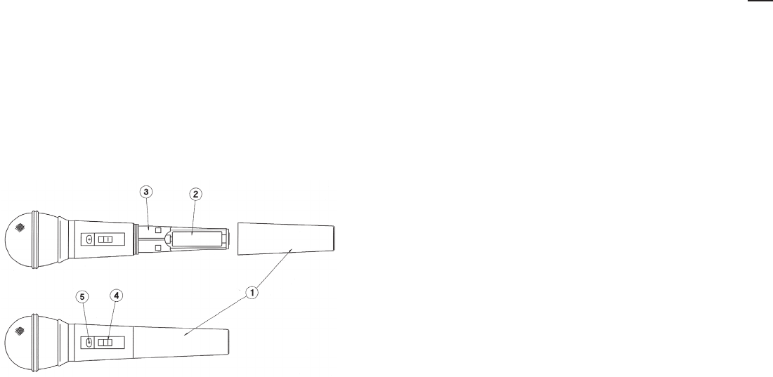
31HT Handheld Microphone Transmitter:
(1) Turn the bottom half of the microphone case counterclockwise until it is
completely off.
(2) Insert one fresh Alkaline “AA” battery into the compartment. Make sure bat-
tery polarity is correct. Then replace bottom half of microphone case and
turn clockwise until snug. DO NOT OVERTIGHTEN.
(3) The frequency label indicates what frequency (in MHz) the transmitter broad-
casts on. The AZDEN receiver in use must be on the same frequency.
(4) 3-Position Switch
Bottom position:OFF - Middle position:STANDBY - Top position:ON
In the “STANDBY” position, the audio is muted.
(5) LED indicator
RED when the switch is in “STANDBY” position - GREEN in “ON” position.
NOTE: Remove the battery if the transmitter is not used for a long period of time.
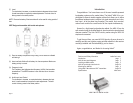
Installing an APS module... (see photo - page 1)
All APS modules install into the APS 25 in the same manner. To
install, first remove the blank panel by loosening the two retaining thumb
screws. Next remove the “shorting board” by pulling it straight out. Now,
simply slide the module into the slot and lightly press until the connector
in the rear engages and the front panel is flush. Last, replace the two
thumb screws and tighten snugly. Any APS module can be inserted into
either slot. Save the “shorting board(s)” for possible later use.
NOTE: If you purchased your APS 25
with one or two modules, they
have already been installed.
The APS 25 Inputs/Outputs and Controls...
A. MASTER VOLUME CONTROL - controls the overall volume of the
APS 25 as well as the LINE OUT (8) connector.
B. TONE - this is a variable frequency high-cut tone control that is pri-
marily used to reduce high-frequency feedback. The control is
essentially flat when turned fully clockwise and reduces more high
frequencies as it is rotated counterclockwise.
C. LED - displays the power state of the speaker. See (4) for details.
1. CHAN A slot - any module can be installed here.
2. CHAN B slot - any module can be installed here.
3. MIC INPUT - plug a wired dynamic microphone in here. This 1/4 inch
jack is designed to accept a low impedance microphone. The input
volume is controlled by the MICROPHONE LEVEL knob (5).
4. OFF/AUTO/ON switch - this controls the power for the speaker after
the MASTER AC SWITCH (12) is placed in the ON position.
• The speaker is essentially OFF with this switch in the OFF position.
The front panel LED (C) will glow Red.
• The speaker will come ON from its standby mode automatically when
any signal is sensed when the switch is in the AUTO position. The
LED (C) will turn from Red to Green. 10 minutes after all audio stops
the speaker will return to its standby mode and the LED (C) will re-
turn to Red.
• The speaker is ON at all times when the switch is in the ON position.
The LED (C) will glow Green.
5. MIC LEVEL - this knob controls the input volume of the microphone
plugged into the MIC INPUT (3). It is always good practice to leave
the control turned all the way down (full counterclockwise) when no
microphone is being used.
6. LINE LEVEL - this knob controls the input volume of anything plugged
into the LINE IN (7) jack.