


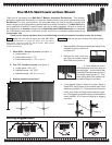
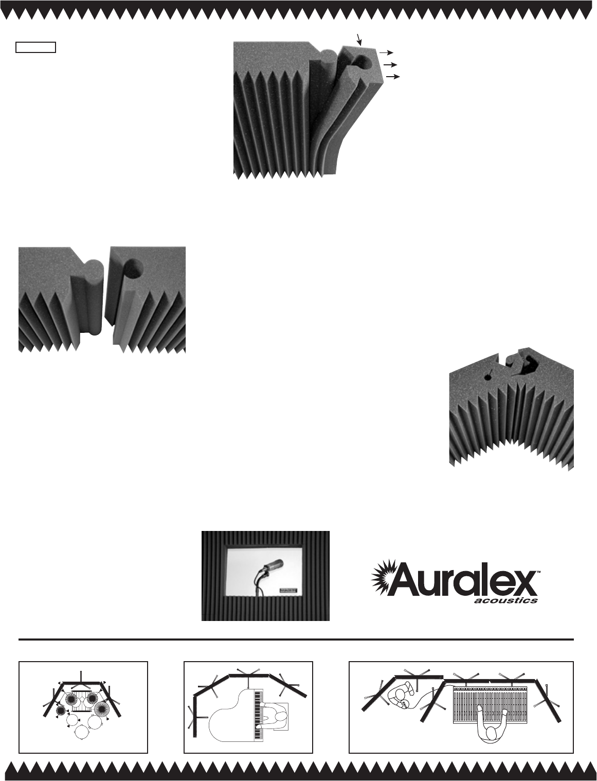
Third. Locking panels together:
The ends of each panel are designed to “peel”
away (see figure 2), allowing the panels to be
locked together. This creates a continuous
acoustical wall. Panels can then be hinged
up to 60°. When removing these pieces, we
suggest labeling both the panel and the end
cap in a location that will be concealed once
connected. This will allow you to replace the
end caps without them being mismatched.
Our cutting tolerance can vary slightly; end
caps that are mismatched with panels may
not exactly match, and thus may not be a perfect t (too
loose). Decide which set of panels are to be interconnected
and remove the adjacent end pieces. Must be male to female
for this to work. If you need to, just ip the MAX-Wall panel
over so the panels
correctly connect
male to female
(figure 3).
If ends of panels
are adjacent, but
hinged greater
than 60° (actually
120° for you math-
ematicians), leave the end caps on and connect the panels
together with long pins (clothing, t-pins, etc.) or purchase
our optional MAX-Wall Corner Couplers. If the ends of the
panels are at the end of your setup, we suggest leaving them
on for appearance reasons!
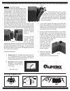
Optional Accessories:
1. Window Unit: 20” x 48” MAX-Wall panel with an 18”
x 12” Plexiglass window (” thick). The MAX-Wall
support stand can be adjusted so you can attach a
microphone gooseneck (as pictured).
2. MAX-Wall Corner Couplers
Designed to allow panels to
be attached at a 90° (80° to
100°) angle.
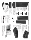
MAX-Wall Tips:
End Cap
Serving Suggestions:
Figure 2
1. Some panels may show a slight
variation in color/shade. This is due to the
direction of the cut from our production saw.
Pull all of the panels out of the box(es) and
mix/match the best combinations. We suggest
the closest matches be used on the same stand
for color consistency.
2. If you need to extend the height of the MAX-Wall
beyond the capabilities of the MAX-Wall support
stand, 5/8” PVC pipe can be placed over the smaller
diameter top of the stand and cut to a height to sup-
port panels above normal height.
3. A more “curved” environment (figure 4). If you desire
the MAX-Wall to “surround” you beyond the normal
hinging of the panels, you can “fracture” the hole
lock in the center of the panel, creating a 45° with
an individual panel. Be aware that the hole lock
can be restored, but may not
be as strong or attractive
as before. The “frac-
tured” panels are
best used when the
ends are interlocked
with other panels to
prevent sagging.
4. Keep the shipping
box(es) for storage if
the MAX-Wall will be
moved around or used intermittently.
Figure 4
Male Female
Figure 3