


Master Level Controls
Each channel is able to control its volume independently
relative to the other channel. At the bottom left of the rear
panel, there are 2 screwdriver adjustment knobs which
correspond to the volume level of the channel identified by
a channel designator below it.
The volume range is labeled Minimum to Maximum and has
1 steps (clicks) at a center detent position as a reference.
Rotate the knob clockwise to increase output, and counter-
clockwise to decrease output.
These adjustments set the master level and if not set up at
initial setup of the AMP200 will or may adversely affect the
performance of the amplifier.
To set the Master Level controls begin by adjusting the front
panel “Volume Trim” to its fully clockwise position. Also set
the front panel “Balance Trim” to its center detent position.
Now adjust both the Left and Right Channel Master Level
controls to set a “Maximum” desired volume for the AMP200
in its application, as well as setting an appropriate “Balance”
from left to right.
Now the front panel Volume and Balance Trim controls can
make fine adjustments to your set up in this application.
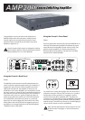
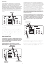
RCA Input
There are a total of 4 RCA inputs on the back panel of the
AMP200. These RCA inputs are labelled as “Line 1 Input” and
“Line 2 Input”. They are also designated with an “R” or an “L”
as Right channel or Left Channel inputs respectively.
“Line 2 Input” should be used as the “primary’ or normal
input for various line level sources that may be available
locally to the amplifier. “Line 1 Input” is a priority switching
input that can be used for a second input, such as, the
output of a second source, and will take over as the primary
input whenever a signal with a minimum of 5mV of level is
present. Whenever, there is an absence of signal at the “Line
1 Input” RCAs the input will revert back to the normal “Line 2
Input” RCAs input signal. An adjustable delay of from 3
Seconds to 15 Seconds is available and can be set to accom-
modate the nature of the source connected to the “Line 1
Input” RCAs.
As an example, if the “Line 1 Input” source was a CD Changer, the
delay could be adjusted to prevent switching back to the “Line 2
Input” source while the changer moves from one disc to another.
Speaker Level Input
The AMP200 also provides a pair of speaker level inputs for those
applications where either of the sources has only speaker level
output signal available. This input may be switched to be used in
place of the Line 1 or Line 2 input.
Mode Switch
To the right of the Master Level controls is a switch labeled
“MODE” with “STEREO” and “BRIDGED” as options. If you will be
connecting one or two pair of speakers to the amplifier, place
the switch in the “STEREO” position.
If you will be using a pair of channels to power a single mono
speaker, place the switch in the “BRIDGED” position, and be
sure to read the section titled “Speaker Terminals” below.
When you are using the amplifier in “Bridged Mode”, the amplifier
is now a single channel Mono amplifier. The two channels have
been internally connected in series by the “Bridge” switch. The
AMP200 is now capable of 250W, bridged into 8 ohms with less
than 0.2% THD+N.
For the amplifier to operate properly in the bridged mode you
should have both the “Right and Left” inputs connected to the
amplifier. The amplifier will sum these signals and create your
Mono source.
NOTE: Both of the “Master Level” adjustments should
be set to the same position, and the “Balance Trim”
should be set to the center or 12 o’clock position for the
amplifier to operate normally in the “Bridged” mode.
NOTE: This amplifier will produce in excess of 300 watts
with a bridged pair of channels. Please verify that your
speakers are capable of handling such power to avoid possible
damage!
Speaker Terminals
Each channel has two pair of multi-way binding post. These are
the red and black screw posts on the rear of the amplifier.
Terminals are provided for “A” and “B” pairs of speakers for each
channel. If you will be using the amplifier as a stereo amplifier
(i.e.- not a bridged amplifier) you will connect the speakers
positive (red) terminal to the amplifiers positive (red) terminal
using the appropriate gauge speaker wire, and the speakers
negative (black) terminal to the amplifiers negative (black)
terminal (immediately below the positive terminal) using the
appropriate gauge speaker wire. If you would like to use one pair
of channels bridged, place the “MODE” switch in the “BRIDGED”
position and use both RED terminals to connect to the speaker.
(See illustration on page 5)
L
R
L
R
Line 1
Line 2
Speaker In
IN
IN
Out
+
+
_
_
RL
Delay
Time
3 Sec 15 Sec
Line 2
Line 1
4