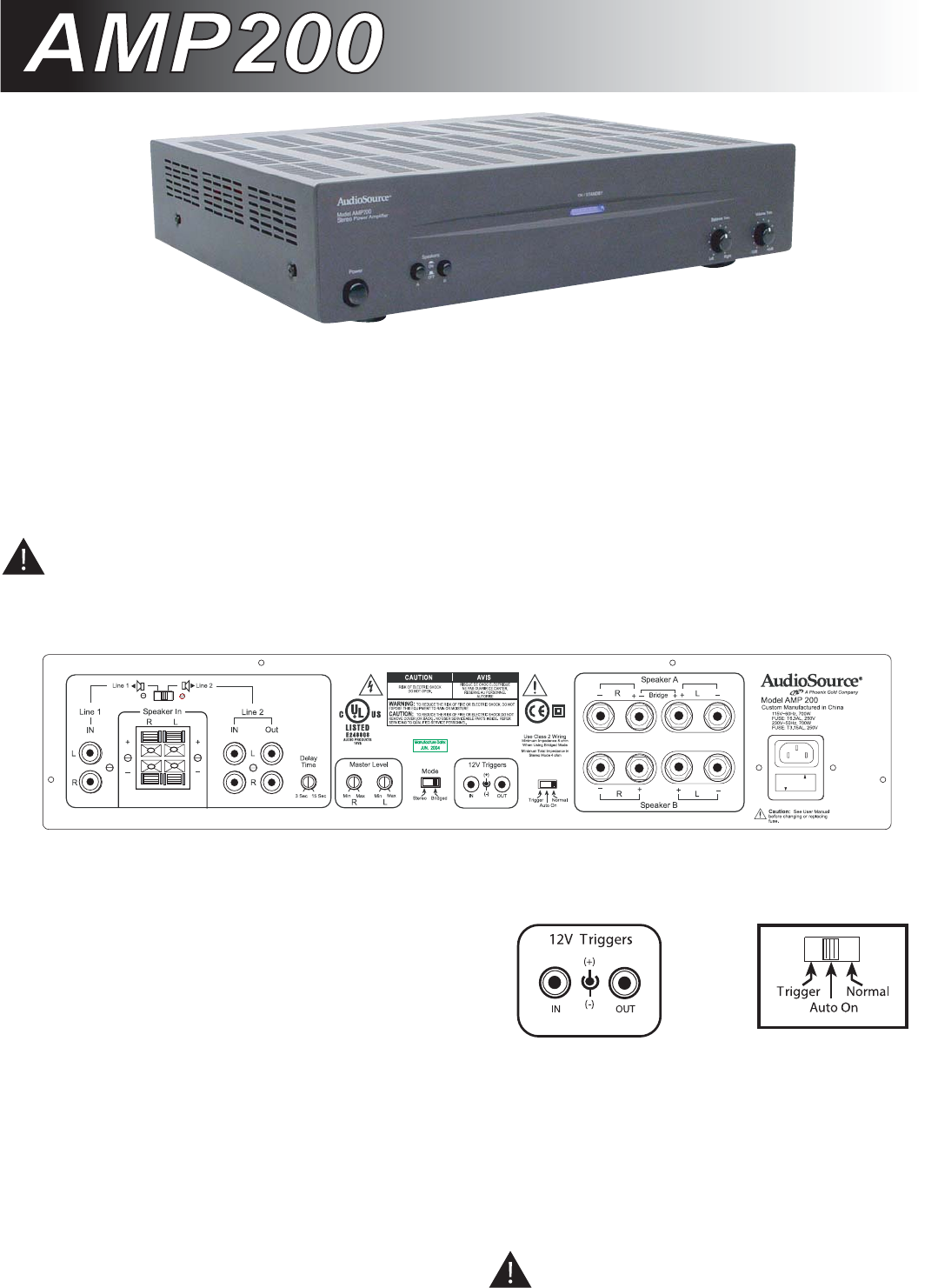
You should use a 3.5mm phone plug in the “IN” connector to
make this connection. The tip of the connector is (+) positive,
and the sleeve of the connector is (-) negative. A second
terminal in the same block is labeled “OUT”. This allows for
remote turn-on of other devices when the AMP300 is powered
on. Use the same polarity for the terminals of this plug. Please
read the owner’s manual for any devices you are attempting to
connect in this manner to ensure compatibility.
Note: The front panel power switch must be in the “ON”
position for the 12V triggers or “Auto ON” features to
operate.
Congratulations on your purchase of the AudioSource
AMP200. Please take a few moments to read this entire
manual, and be sure to retain this document for future
reference. Please read and observe all safety instructions
detailed on page two (2).
Note: If any part of this product is damaged or missing,
please call your dealer or Phoenix Gold Home Products
directly at 800-435-7115 or 503-286-9300.
Source Switching Amplifier
Source Switching Amplifier
Using the Controls / Front Panel
Power
The front panel switch will manually switch the AMP200 on or
off. A blue LED behind the faceplate lens indicates its power
status. Whenever the amplifier’s power switch is in the “ON”
position and the amplifier is in “Active” status the lens is
illuminate Blue. If the amplifier is “ON” but in the “Standby”
status the lens is illuminated RED.
Using the Controls / Back Panel
Power
The AMP200 can be turned on and off independently via a
switch on the front panel, by signal sensing, or remotely by a
triggered DC input. There is a switch located on the lower
edge of the rear panel of the amplifier to select how you
would like to turn on the AMP200. If you would like to control
the unit’s power on / power off status manually from the front,
place the switch in the “Normal” position. If you would like to
control the unit’s power on / power off status by means of
signal sensing, place the switch in the “AUTO ON” position. If
you would like to control the unit’s power on / power off
status by a DC remote trigger, place the switch in the “TRIG-
GER” position, and connect the remote triggering wire and
ground from your triggering device to the terminal labeled
“TRIGGER IN” next to the switch.
3
110V
220V
Fuse Holder


