


– 11 – AtlasSound.com
Specifications are subject to change without notice.
Owner’s Manual PA1001G Power Amplifier
1601 Jack McKay Blvd. • Ennis, Texas 75119 U.S.A.
Telephone: 800.876.3333 • Fax: 800.765.3435
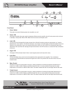
Placement and mounting of the PA1001G
Turn off all equipment before making connections. Mount amplifier in a standard-width 19” rack. It can be mounted above
or below anything that does not generate excessive heat. Although the unit’s chassis is shielded against radio frequency
andelectromagneticinterference,extremelyhighfieldsofRFandEMIshouldbeavoided.
Ventilation - The appliance should be situated so that its location or position does not interfere with its proper ventilation.
For example, the PA1001G should not be situated on sealed cabinet or on a shelf with obstacles on it that may impede
the flow of air through the ventilation openings. It is recommended that if the amp is not used in an open air pole mount
that it be rack mounted into a commercial rack.
Heat - The PA1001G should be situated away from heat sources such as radiators, heat registers, stoves, or other appli-
ances (including amplifiers) that produce excessive heat. Ambient temperatures should not exceed 113° F (45°C) when
equipment is in use.
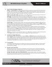
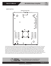
Video Pole Mount – The PA1001G is ideally suited to be used in board or class room video / audio applications. The
PA1001G incorporates a 2” diameter hole trough the center of the chassis to allow for sharing the same support pole that
standardceilingvideoprojectorsmountto.EnclosedwiththePA1001Gisthesupportbracketandhardwaretomountthe
PA1001G to a pole. Follow the below instructions for proper installation.
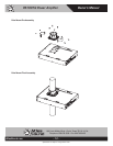
1. Make sure the pole you are mounting the amp to does not exceed 2” or 51mm. Common pipe to use for video
projector mounting is 1.5 ID plumbing pipe. The OD for this pipe is 1.9” or 49mm.
2. Make sure the PA1001G is unplugged from the AC source.
3. Remove the top and bottom hole plugs.
4. Secure the pole support bracket using the four screws as shown in the diagram below. Note: the support bracket may
be installed on the top or bottom of the amplifier.
5. Slide the amplifier up the pole. Do not force the amp onto the pole. Pay attention to orientation of the amp.
6. Secure clamp by tightening the two 1⁄2 clamps around the support bracket. Do not over tighten.
7. Once the PA1001G is secured to the pole DO NOT mount any additional PA1001Gs to the same bracket. The sup-
port bracket is only designed to support one PA1001G.