


Specifications are subject to change without notice
AtlasSound.com
1601 JACK MCKAY BOULEVARD ENNIS, TEXAS 75119 U.S.A. • TELEPHONE: (800) 876-3333 • FAX: (800) 765-3435
©2005 ATLAS SOUND LP Printed in U.S.A. ATS002102 RevC 9/05 PP
OWNER'S MANUAL
CP700 COMMERCIAL
POWER AMPLIFIER
13
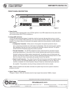
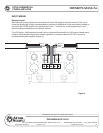
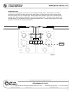
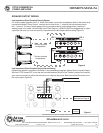
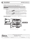
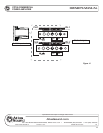
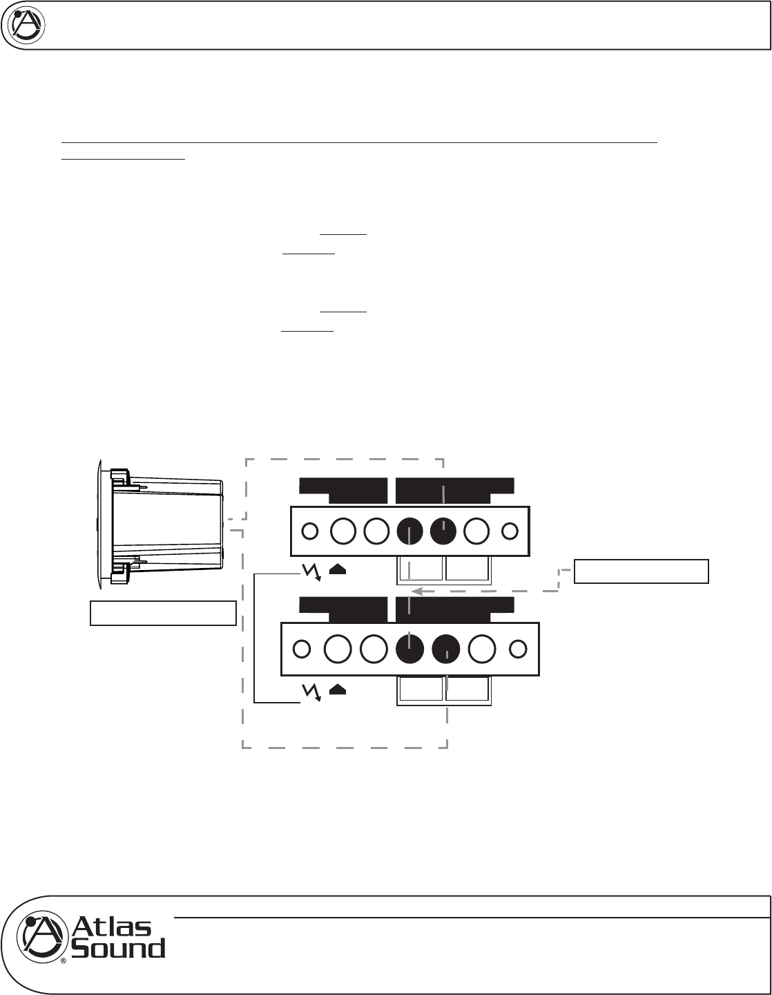
Bridge Mono Transformer Coupled Output Wiring for 140V/200V Output Operation
The CP700 can be configured to drive 140V and 200V speaker lines.
Please observe all necessary safety precautions as the potential for electric shock at the speaker
terminals is present.
With the CP700 turned off, move the rear mounted selector switch to the "Bridge" position and connect
the input signal to channel one. Connect your speaker load across the "+" terminals of both output
terminals as follows:
• 140V Operation - Connect the positive lead of the speaker load to the channel ONE 70V
positive "+" terminal, the negative speaker lead connects to the channel TWO 70V positive "+"
terminal. Connect a suitable jumper wire between the two terminals labeled "0." Consult your
local codes to determine if Class I wiring is required (Figure 11).
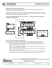
• 200V Operation - Connect the positive lead of the speaker load to the channel ONE 100V
positive "+" terminal, the negative speaker lead connects to the channel TWO 100V positive
"+" terminal. Connect a suitable jumper wire between the two terminals labeled "0." Consult
your local codes to determine if Class I wiring is required (Figure 12).
Caution! A high voltage potential exists across the two "+" speaker terminals when operating in
any Bridge Mode application!
Figure 11
CH-1 CH-1
- 100V +
-+
70V
-+
25V
8, 4, and 2 Ohms
AUDIO TRANSFORMER
DIR. OUTPUT ISOL. OUTPUT
-+ 70 1000
BRIDGE
MONO
+
CH-2 CH-2
- 100V +
-+
70V
-+
25V
8, 4, and 2 Ohms
AUDIO TRANSFORMER
DIR. OUTPUT ISOL. OUTPUT
-+ 70 1000
BRIDGE
MONO
-
Note Jumper
To 140V speaker load