


3
Instruction Manual
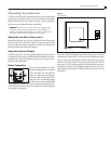
Subwoofer Rear Panel
BYPASS
LOW-PASS
ON
AUTO
PHASE
NORMAL
INVERT
40
160
100
LOW-PASS
60
RIGHT
L/MONO
OUTPUT
INPUT
STATUS
ON OFF
AC INPUT
50-60Hz 300W MAX
220-240V110-120V
FOR 110-120VAC, USE 2.5AL 250V FUSE
FOR 220-240VAC, USE 1.25AL 250V FUSE
FOR CONTINUED PROTECTION AGAINST RISK OF FIRE,
REPLACE ONLY WITH SAME TYPE AND RATING OF FUSE
U.S. Patent #5,075,634 and
5,510,753 Patent Pending
AVIS: RISQUE DE CHOC ELECTRIQUE-NE PAS OUVRIR
RISK OF ELECTRIC SHOCK
DO NOT OPEN
CAUTION
WARNING: TO REDUCE THE RISK OF FIRE OR ELECTRIC SHOCK.
DO NOT EXPOSE THIS APPLIANCE TO RAIN OR MOISTURE.
DOUBLE INSULATION - WHEN SERVICING,
USE ONLY IDENTICAL REPLACEMENT PARTS
A
Z
A
R
D
S
S
S
E
COMPLIANT
E
S
R
H
I
O
T
R
I
C
T
N
O
F
O
U
C
B
S
T
A
N
U
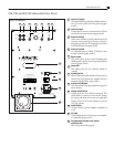
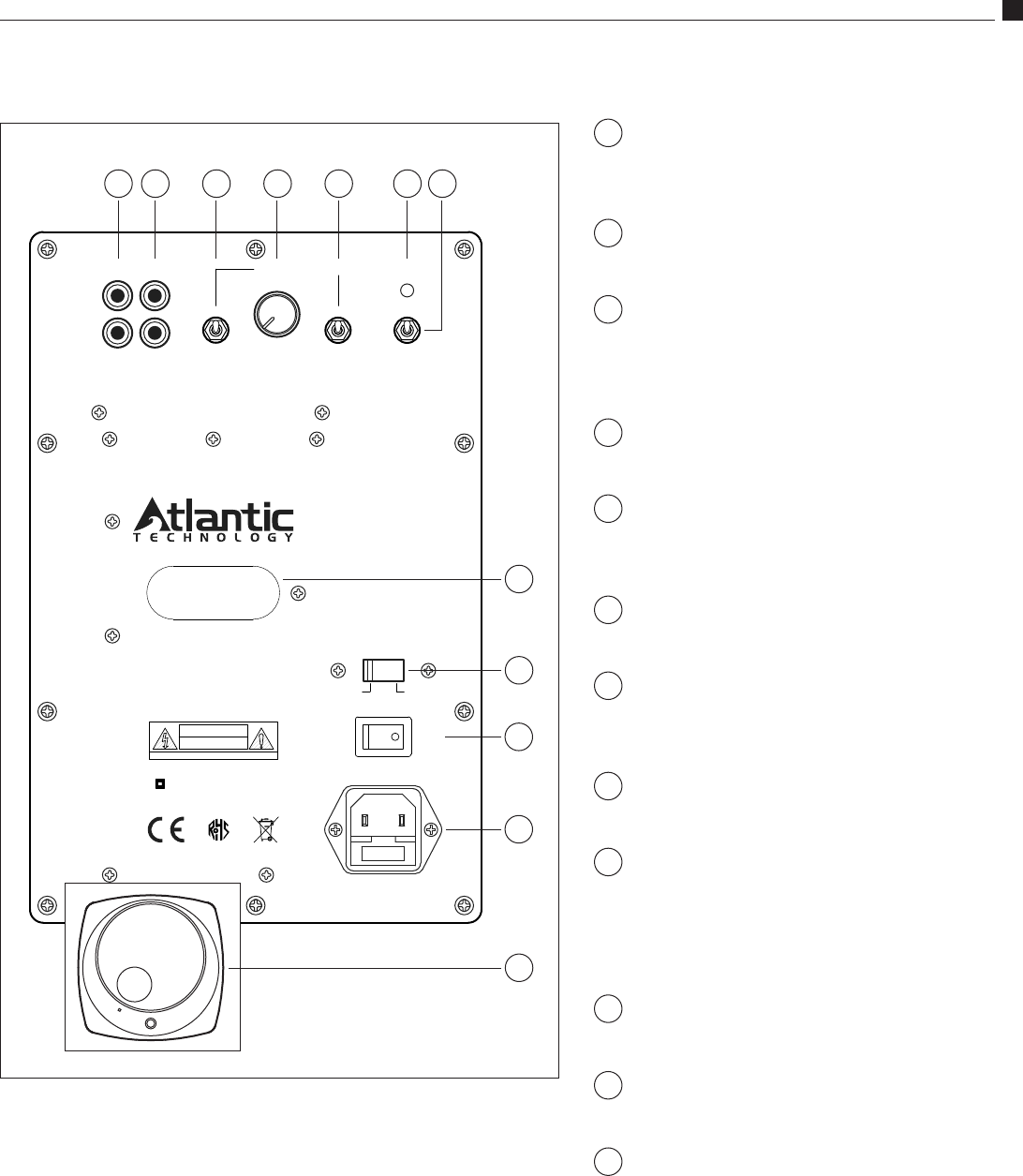
Low Level Output
The outputs allow daisy chaining of multiple subwoof-
ers, or as a return path back to the processor. (pages
4 and 5)
Low Level Input
Use the input to connect to the subwoofer or LFE line
out from your processor/receiver. (pages 4 and 5)
Crossover Switch
When in the NORMAL position, adjustment of the
crossover can be made by the Crossover Control. If
being fed a pre-filtered or THX signal, place the switch
at the BYPASS position. (pages 4 and 8)
Crossover Control
An adjustable (40Hz to 160Hz) @ 18dB per octave
low-pass crossover. (pages 4 and 8)
Phase Switch
This switch allows precise acoustic matching with
satellite speaker systems whose output may be phase
reversed. (pages 4 and 9)
Status LED
This will be green for "on" condition, amber for
"standby"
Standby Switch
When in ON position, the amplifier will always be on.
When in the AUTO position, the amplifier will be in
Automatic Standby Mode. (pages 4 and 8)
Product Serial Number
Write this number in the space provided on page 2 for
future reference.
Voltage Select Switch
Voltage switch for use in different countries. This
switch will be set when you receive the unit. Change
this setting only when you are sure your application
requires it. For US, the switch should be set to the
110-120V position.
On/Off Switch
Use this switch to turn the amplifier completely on
or off.
AC Input
Use the included power cord to connect your amplifier
to a wall outlet. (pages 4 and 5)
Front Mounted Variable Level Control
and Status LED
Shown in greater detail on page 8.
1
4
3
2
10
8
9
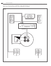
224, 334 and 444 SB Subwoofer Rear Panel
Figure 1 - 224 SB shown
1
9
11
8
7
5
72 3 4 5 6
6
11
12
10
12