


7
Operating Manual - PQX 571 and PQX 572 Parametric Equalizer
2. With the entire PA hooked up and turned on,
slowly increase the sound level at the mixer un-
til feedback is heard, then lower the level by about
3 dB so that feedback does not continue.
3. Start with one of the PQX filters by setting
the level at 0, bandwidth set fairly sharp (about
.3 oct.), and adjust the frequency control to where
you estimate the predominate feedback frequency
to occur.
4. Push in the filter’s EQ switch and increase its
level control by about +6 dB. Now “sweep” the
frequency around where you have estimated the
feedback frequency until feedback occurs. Once
you have induced the feedback by boosting its
frequency, quickly turn down the filter’s level
control to about -6 dB to suppress or “notch out”
the feedback frequency.
5. Again slowly increase the master level at the
mixer until feedback is heard. If a new feedback
frequency is heard, then repeat step 3 to find and
suppress the new frequency. If the original feed-
back frequency is still heard, then adjust the first
filter’s level even lower. The bandwidth control
may be adjusted full clockwise to produce a very
sharp notch so that a severe feedback frequency
can be attenuated by as much as 15 dB without
degrading the frequency response with noticeable
notches. Note: Very sharp bandwidth lowers the
maximum equalizer input level because of the
high filter gain necessary to obtain such a nar-
row bandwidth. Only use bandwidth control full
CW (.05 Octave) in severe cases.
6. Continue this iterative process of increasing
the mixer’s master level and finding, then sup-
pressing feedback frequencies until a de-
sired sound system gain-before-feedback
level has been achieved.
6.4 Console Channel Equalization
Many mixing consoles provide only
simple equalization for individual channels. If
your console has channel inserts, you can patch
your equalizer into a channel that is used for some-
thing important, and use it to tailor the sound of
this channel exactly the way you want.
6.5 Large Room Equalization
Large rooms tend to suffer from multiple reflec-
tions with long time delays, long reverberation times, and
“ring-modes”, all of which lead to reduced intelligibility
and a generally “muddy” sound. As sound travels long
distances through the air, high frequencies are attenuated
more than low frequencies. In general, large rooms ben-
efit from some low frequency shelf roll-off, high frequency
shelf boost, and attenuation of ring mode frequencies by
the parametric filters.
6.6 Small Room Equalization
Small rooms need less equalization than large
ones. However, with reflective surfaces so close together
it is more likely to encounter high frequency feedback
problems. Finding and critically notching out these of-
fending “hot spots” is precisely what the PQX equalizer
does best. Use the narrowest possible bandwidth, and as
always, avoid over-equalization.
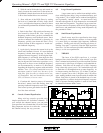
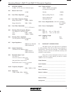
7. THEORY
The heart of the PQX equalizers is a unique
bandpass filter circuit. Basically a “state-variable” type, this
filter is trimmed and optimized to provide excellent transient
response and a wide range of frequency and bandwidth ad-
justment. Each filter can be tuned over a 100:1 frequency
range (about 6.6 octaves) and a 70:1 bandwidth range with
no more than a 2 dB amplitude error at center frequency. At
its sharpest setting, the filter has a “Q” of about 35 and gen-
erates a response curve with 3 dB points only 1/20 octave
apart, making feedback control possible with no audible side
effects. Each filter is placed in the feedback loop of a sum-
ming amplifier to produce the desired frequency response.
Since a separate summing amplifier is used for each band,
no interaction between bands occurs.
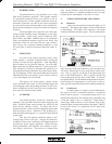
PQX Block Diagram
-
+
+
-
CLIP
DETECTOR
PEAK
HIGH
20-20K 20-20K 20-20K 20-20K 20-20K
FILTER FILTER FILTER FILTER FILTER
PAR. PAR. PAR. PAR. PAR.
IN
IN IN
IN
IN IN
IN
EQ
EQ EQ
EQ
EQ EQ
EQ
QQQQQFRFRFRFRFRFRFR
+/- +/- +/- +/- +/- +/- +/-
FILTER
SHELF SHELF
LOW
OUTPUT
IN
OUT
EQ
GAIN
INPUT
BALANCED