


Operating Manual - PQX 571 and PQX 572 Parametric Equalizer
4
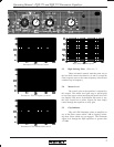
5.2 Parametric Filters (Filters No. 2-6)
1. Range Switch
Each parametric filter has a normal center fre-
quency range of 200Hz-20KHz. Depressing the range
switch divides the center frequency by 10, providing a
range of 20Hz-2KHz.
2. Level Control
The band of frequencies selected by the frequency
and bandwidth controls are increased or decreased up to
15dB by this control.
3. Frequency Control
This outer concentric knob adjusts the center fre-
quency of the filter action. Tick marks on the face panel
are calibrated to ISO 1/3 octave center frequencies.
4. Bandwidth Control
This inner concentric Knob allows control of the
width of frequencies around the center frequency (some-
times called “Q”), and is a key reason parametric equaliz-
ers are such a precise tool. With it, you can affect a wide
(3.3 octaves) response, or a narrow (.05 octaves) band.
To give an example, you could effectively boost or cut by
15dB a middle C on the piano without affecting the adja-
cent B or D at all!
5. EQ In/Out Switch
The individual filter is engaged by depressing this
switch. Since the filter is bypassed when the EQ switch
is out, it is recommended that the EQ switch be out when
no filter action is required. This is preferable to “zero-
ing” the level control when considering optimum noise
performance.
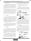
4.3 Grounding
The terminal strip has two ground con-
nections, one for input ground and one for chassis
ground. The equalizer is shipped with a jumper
strap connecting these two grounds. Normally,
this strap should be left in place so the chassis
and input grounds are connected. In a rack-mount
installation where the equalizer is connected to
other equipment with unbalanced inputs or out-
puts, and the rack itself provides a good electrical
connection between the equalizer chassis and the
other equipment, it may be desirable to remove this strap
to isolate the input ground from chassis ground and avoid
a ground loop. Unless you have such an installation and
have a hum problem you can’t solve by other means (ie:
using balanced input and output connections), leave the
ground jumper strap in place.
5. CONTROLS
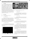
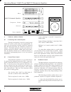
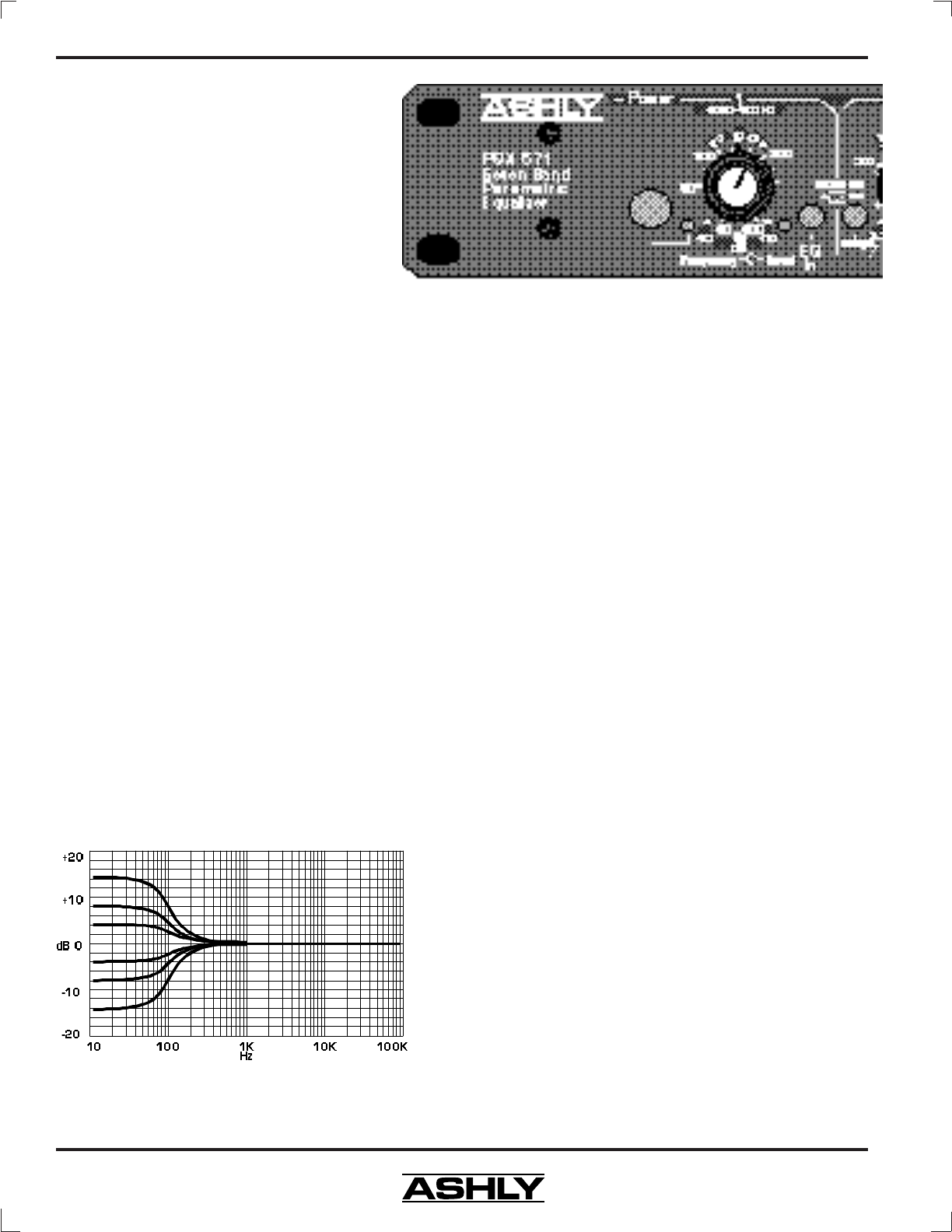
5.1 Low Shelving Filter (Filter No. 1)
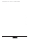
1. Low Shelf Level
The nature of a shelving filter is such that the fre-
quency response ramps up to a plateau and then levels off
again, hence the term “shelf”. This level control knob ad-
justs the boost or cut of the signal below the tuned filter fre-
quency as selected by its outer concentric frequency knob.
The level which is indicated on the panel dial is the decibel
level of the flat portion of the shelf. (see drawing)
2. Low Shelf Frequency
This control adjusts the frequency below which
the shelving filter affects the level. The frequency which
is indicated on the panel dial is the midpoint of the shelf’s
sloping response.
Low Shelf Level Response