


6
Operating Manual - DPX-100 Graphic Equalizer - Compressor/Limiter
the double time constant, release from gain reduction af-
ter a brief transient is always fast, with a slower release
after a sustained overdrive.
6.6 OUTPUT LEVEL
Output level control is provided to fully cut or
restore up to 18 dB of system gain. For unity gain, set
the control to 0. NOTE: When the compressor/limiter is
switched out, the output control still functions.
6.7 IN/OUT SWITCH
This switch enables you to quickly hear the com-
pressor/limiter in or out of the audio chain. When the
switch is in the out position, all limiting and compres-
sion controls and functions are bypassed, with the excep-
tion of the gain and output controls, which continue to
function as straightforward level controls.
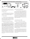
6.8 THRESHOLD/GAIN REDUCTION DISPLAY
As soon as the threshold level is reached, the yel-
low LED illuminates. Depending on how far the input
level rises above threshold, successive red LED’s will il-
luminate, indicating gain reduction. Gain reduction can
best be described as the difference between input level
and the resulting change to output level. For signals
below threshold, there will of course be no gain reduc-
tion, that is, a 10dB increase in input will yield a 10dB
increase in output. For signals above threshold however,
output level will increase only to the extent that the ratio
control allows. With a high ratio, say 20 or so, it will take
20dB of increased input level to increase output level by
1dB. With a gentler ratio of 3:1, input signals above
threshold will be “gain-reduced” at the output by 1/3. In
other words, with threshold set at 0dB, a signal peak at
+12 dBV that is 3:1 compressed (ratio at 3) will produce
only +4 dB (12÷3) at the output, and 8 dB of gain reduc-
tion has occurred (12 dBV input minus 4 dBV output=8
dB reduction.)
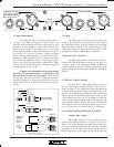
6.9 INPUT/OUTPUT METER SELECT
While the Gain Reduction display accurately rep-
resents the action of the limiter, comparing input to out-
put levels in real time is somewhat more intuitive, and is
made simple using the input/output meter select switch.
The input meter takes its signal just after the gain con-
trol, and will indicate input signal level regardless of out-
put levels or limiter settings. The output meter display
takes its signal from the actual output of the unit, so ev-
ery control that affects the output will also have an effect
on output meters. Used in conjunction with the gain re-
duction meters, input/output meters prove to be an ex-
tremely useful diagnostic tool when working with system
dynamics and level control.
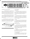
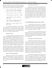
7. CONNECTIONS AND CABLES
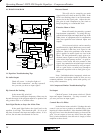
7.1 Balanced vs. Unbalanced Audio Connections
Balanced signal connections are preferred in pro
audio applications because of their improved immunity
to induced hum and noise. A properly shielded and wired
balanced input stage on any audio product will reject most
unwanted noise (RFI, EMI) picked up by the cable, as
well as minimize ground loop problems. Therefore it is
always advantageous to use balanced connections when
running signal more than ten or fifteen feet, although par-
ticularly noisy environments may require that even short
patch cables be balanced.
Unbalanced connections are used mostly for short
distance, high level signals (0dBu nominal). Most exter-
nal EMI noise pick-up will be masked under the noise
floor of the signal, assuming there is little or no gain fol-
lowing the unbalanced signal. If a gain stage does follow
a signal, or if externally sourced noise persists, use bal-
anced connectors.
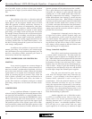
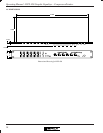
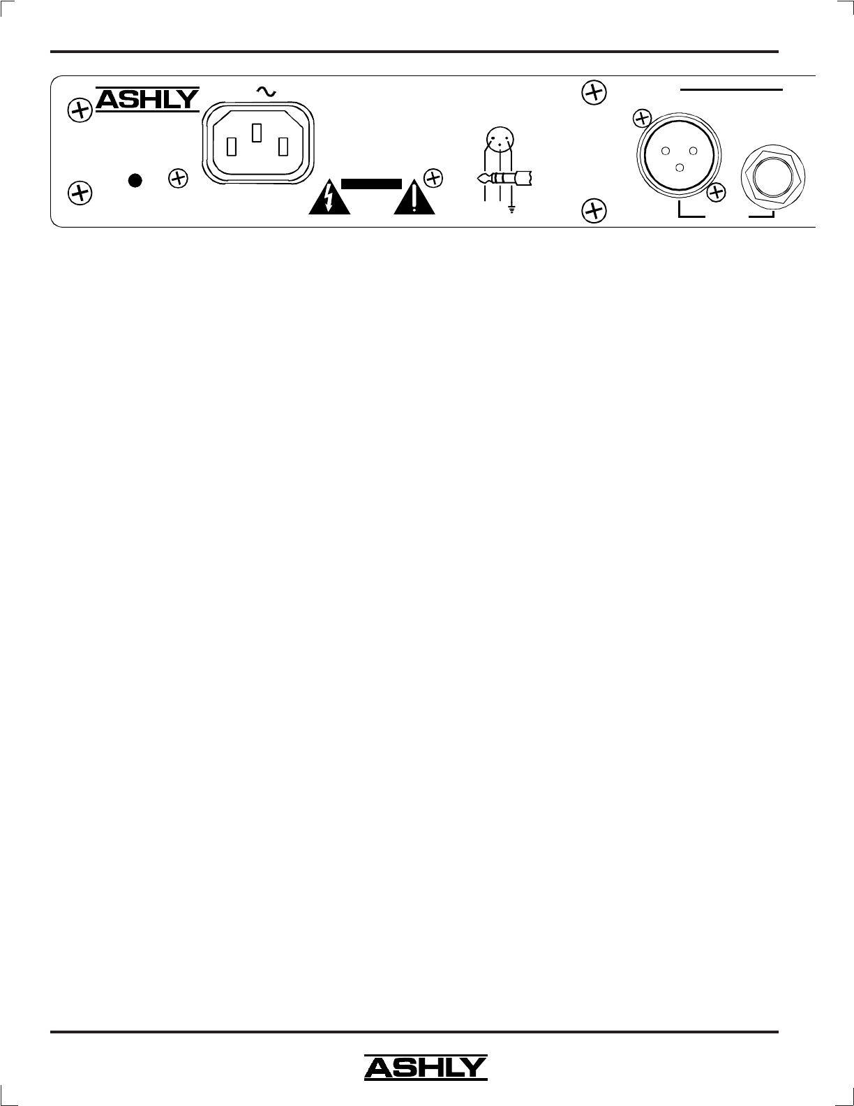
Model DPX-100
Made In USA
100-120VAC
50-60Hz 12W
(-)(+)
2
3
1
INPUTS are Active Balanced.
OUTPUTS May Be Wired
Balanced Or Unbalanced.
TIP = Detec
(Use
M
RIN
G
Output
Com
p
AC
Risk of Electric
Shock. Do
Not Open
CAUTION
XLR
Female
Shown