


4
Operating Manual - DPX-100 Graphic Equalizer - Compressor/Limiter
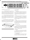
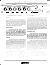
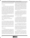
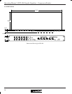
5. EQ CONTROLS
5.1 EQ Boost/Cut
The individual equalization faders adjust the
boost or cut at each filter frequency. By adjusting a com-
bination of faders, an overall frequency response can be
developed and the physical position of the faders will give
an approximate visual indication of this response.
5.2 Gain
The gain control adjusts the overall gain of the
equalizer when the EQ switch is “in”. It is generally used
to compensate for level changes due to the equalization
process, but can also allow the equalizer to adjust overall
system level and gain structure. Overall gain with this
control is from +6dB to -∞.
5.3 Range
This switch selects the operating range of the
individual equalization faders to either ±15dB or ±6dB.
The ±15dB settings should be used when much equaliza-
tion is needed. The ±6dB setting allows finer resolution
on the fader settings.
5.4 HPF (Hi-Pass Filter)
The high-pass filter can be used to supplement
the frequency response achieved by the bandpass filters.
It’s function is to “roll off” low end response to eliminate
subsonic interference like wind noise, floor rumble, and
boomy microphone pops. The high-pass frequency is fixed
at 20Hz with an 18dB/octave slope.
5.5 EQ In/Out
This switches out the boost/cut controls and EQ
gain adjustments. This way, the effect of any equaliza-
tion can be compared to a “flat” response. This switch
does not defeat the high-pass filter.
5.6 Sig and Clip LEDs
The signal present LED comes on when a signal
greater than -20dBu arrives at the EQ input. The clip
LED indicates any EQ signal level exceeding +19dBu.
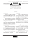
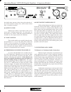
4. MECHANICAL INSTALLATION
The DPX-100 mounts in a standard 19 inch
equipment rack. The mounting screw threads vary with
different rack manufactures and you should refer to your
rack instructions for proper hardware. An oval head or
flat head screw with a plastic countersink washer is pre-
ferred to protect the finish of the DPX-100 under the screw.
This unit is housed in a rugged steel case and
will tolerate moderate abuse. However, for road systems
which may be dropped or otherwise subjected to extreme
forces, we recommend some rear support for the chassis
to prevent bending the front panel the front panel when
these forces occur.
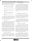
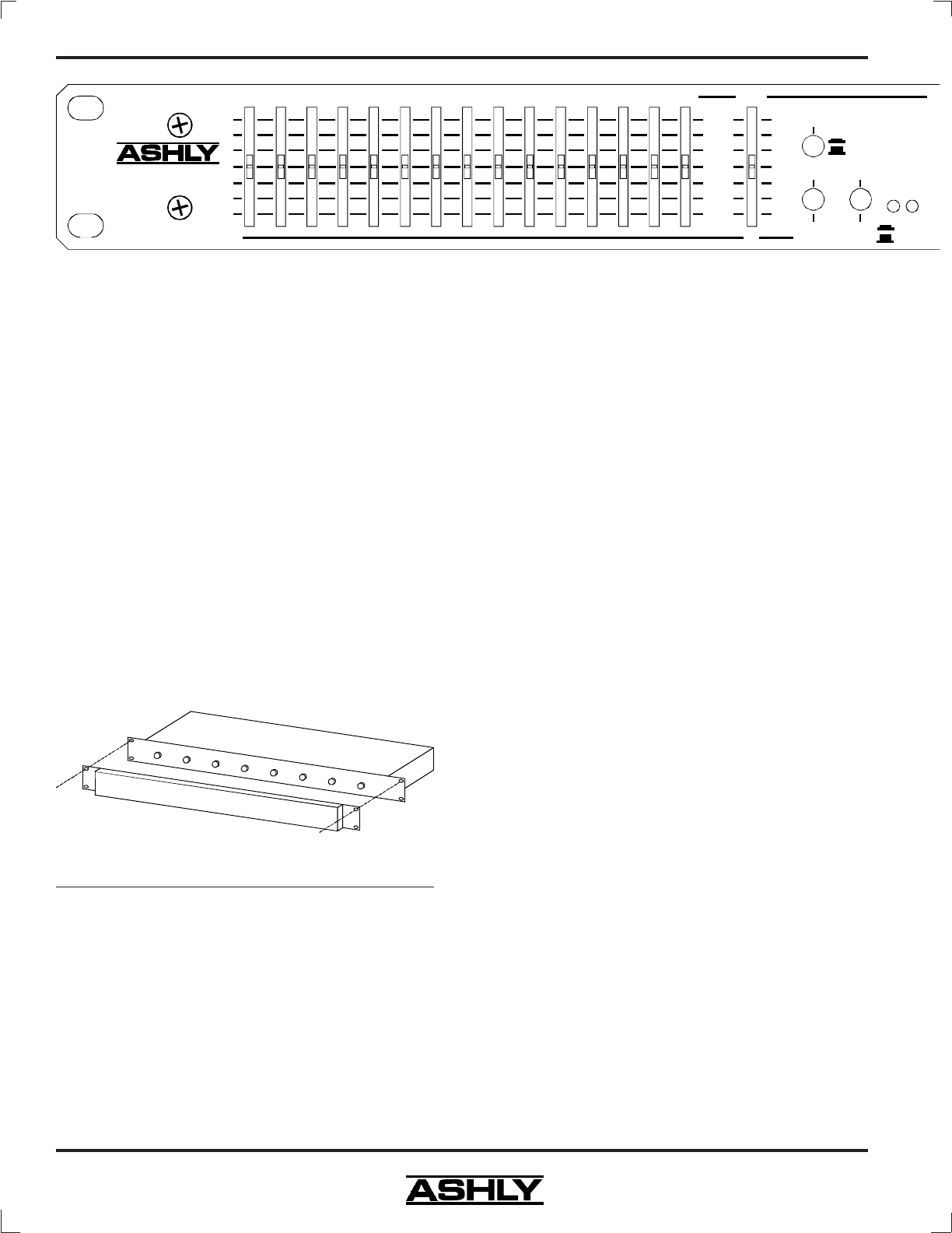
For installations where it is desirable to protect
the front panel controls from tampering or accidental
misadjustment, use the Ashly security cover. Installation
is simple and does not require removal of the equipment
from your rack. See your Ashly dealer for details.
HPF
EQ
20Hz
Out
In
Out
10K
Gain
6.3K16K4K2.5K1.8K1K630400250180100634025
0
+2
+4
+6
-3
-9
-
∞
+15
+10
+5
0
-5
-10
-15
dB
Sig Clip
Range
±6dB
±15dB
Model DPX-100
Graphic Equalizer
Compressor/Limiter
Ashly Security Cover Installation