


4
3. Positioning of the E-A-RTONE
®
When positioning the E-A-RTONE
®
unit on the subject, avoid sound tube contact with the subject’s clothing. Always use E-A-
RLINK
®
tips in both ears, or block the opposite ear with an E-A-R
®
foam earplug.
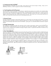
4. Cord Assembly and Unit Placement
The cord assembly is zip-cord constructed. If more distance is needed between transducer cases carefully cut the insulation bridge
between the two cords and separate them to the desired distance. The proper location for the transducer cases is on either side of the
neck, not on the head. The metal clip equipped with a Velcro disk is intended to be used on the collar. A Velcro strap is also
supplied to make an optional neck loop. Attach one end to each of the cases. The resulting loop can be positioned behind the neck
with the cases resting on the shoulders and the cord in front hanging down the chest.
5. Blocked Tubing
If the clear sound tube is partially or fully blocked with fluid, wax, or other material, the sound output will be affected. To remedy
the problem, take the sound tube off at the case nipple and either blow air or push a thin wire through the tube. If the tubes turn
yellow or become damaged, replace them with new E-A-RTONE? specific parts. It is recommended that the sound tubes be replaced
annually.
6. Tubing Characteristics
The consequences of changing the length of the front tubes will be a change in the frequency response of the E-A-RTONE
®
unit.
The inner diameter, length and material used in the sound tubes have been carefully monitored by Auditory Systems to achieve
maximum accuracy, background noise attenuation and proper frequency response. If replacement sound tubes are needed, use only
Auditory Systems approved parts.
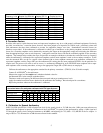
7. Pure Tone Calibration
When the E-A-RTONE
®
3A Insert Earphone is to be used as the primary transducer, the audiometer should be recalibrated using the
reference thresholds provided in the standard ANSI S3.6-1996. The standard presents reference thresholds for the HA-1, HA-2 (DB
0138) and Ear Simulator 2cc couplers. However, the Bruel & Kjaer 2cc DB-0138 (HA-2) coupler will simplify the calibration
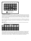
procedure and is recommended. Reference thresholds for DB-0138, IEC 711, and HA-1 couplers are presented below. Should
calibration be performed for an audiometer currently calibrated towards ISO-389, the reference thresholds in a 2cc DB-0138 coupler
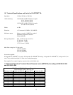
should be used. In order to calibrate the audiometer for direct readings of the hearing thresholds in dBHL using the reference
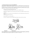
thresholds, the following procedure is recommended. The instrumentation required is a Sound Level Meter with an appropriate
condenser microphone calibrated according to the manufacturer’s specification. To the microphone, a 2cc coupler, Bruel & Kjaer
DB-0138 is attached. The front tube of the E-A-RTONE
®
earphone is connected directly to the coupler (see illustration). Set the
intensity dial on the audiometer to 70 dBHL and adjust the output from the audiometer to the SPL-values given for the different test
frequencies in the table below. Repeat the procedure for all available test frequencies and in case of a dual channel audiometer, for
both channels.