


BIAS ADJUSTMENT
WARNING: Hazardous and potentially
lethal voltages! The Bias adjustment
procedure described below involves
working with equipment covers off and
power applied, exposing the operator
to potentially hazardous or lethal volt-
ages. These tests and adjustments
should be performed only by qualified
personnel with the proper testing
equipment and training.
The Anthem AMP 1 has been designed to give many hours
of listening pleasure and should only require biasing at
tube replacement time.*
Should one of the EL34 output tubes fail or otherwise
require replacement, it will be necessary to adjust the out-
put stage bias current.
The factory set bias current of 40 ma per tube is a good
compromise between long tube life and low distortion. For
the highest performance the current may be increased to
50 ma per tube, of course at the expense of output tube
longevity.
Bias current is measured by sampling the voltage drop
across a 10 ohm resistor connected in the cathode circuit
of each output tube. Using Ohms law E=lxR we can see
that 40 ma current results in a 0.4 volt drop across the
10 ohm cathode resistor and 50 ma is 0.5 volts. For setup
below, 40 ma or a measurement of 0.4 volts is assumed.
A suitable analog or digital multimeter (20,000 Ohms/Volt)
capable of accurately measuring 0-2 Volts DC. eg. Fluke
77 DMM or a Simpson 260, is required.
1. Disconnect the power cord and allow the amplifier to
cool 15 minutes before removing the top cover.
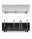
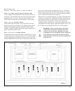
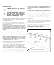
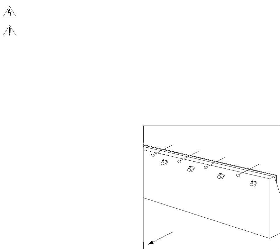
2. After removing the top cover, with the front end of the
chassis facing you and referring to Fig. 6, observe the
location of four test points TP-1, TP-2, TP-3 and TP-4.
These are located left to right along the the top edge of the
main printed circuit board assembly. Also note the position
of the four potentiometer adjustment shafts protruding
from the rear of the PCB mounting bracket. The poten-
tiometers from left to right are VR1, VR2, VR3 and VR4.
3. Connect the multimeter’s negative test lead to the AMP
1’s left channel output COM or black binding post on the
rear panel.
4. Carefully apply line voltage to the amplifier and observe
that all the tube filaments light. As the amplifier is warming
up touch each test point, TP-1, through TP-4 in succession
with the positive meter test probe, noting the voltage at
each point is less than or equal to 0.4 volts. Adjust the
corresponding potentiometers VR1 through VR4 to main-
tain voltage at 0.4 volts at each test point over a twenty
minute period.
5. After 20 minutes if no further movement in the test point
voltage is observed, then disconnect the amplifier from the
power source and replace the top cover.
*Optional periodic checks of the bias may be made every
500 hours or so. Dramatic changes in bias over a 500
hour period generally indicates that the output tubes are
becoming weak and should be replaced.
9
TP-4
TP-3
TP-2
TP-1
VR4*
(for V7)
VR3*
(for V6)
VR2*
(for V5)
VR1*
(for V4)
PCB Mounting
Bracket
Amp Rear
* To increase bias turn knobs counterclockwise.
FIGURE 6
Adjustment of the output tube bias.