


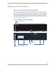


Wiring and Connections
6
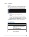
Tango Amplifiers
Cabling Instructions
This installation uses low voltage cabling similar to telephone and alarm wiring, and as such does not
commonly have very many restrictions on their installation. However rules may vary in different regions.
Cable Type
The Tango Amplifier is cabled using standard 4-conductor speaker cable originating at the Tango Controller,
passing through the Keypad, and terminating at the speaker location. AMX recommends using a bundled 4-
conductor 16-gauge stranded copper wire in a single continuous run.
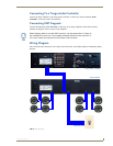
Connecting Zone Outputs (Speakers)
SWT Connectors
SWT cabling follows a specific pinout configuration that is labelled on the Tango Amplifier, Controller,
Metreau keypads, and other Matrix devices, as shown in FIG. 2.
Connecting SWT Speakers
Matrix Audio SWT Speakers are different from any other speaker available on the market. They allow you to
control a single zone of audio without a keypad being installed. Therefore, some different wiring practices
must be considered for proper operation and control.
This is achieved by “daisy-chaining” from the first speaker to the second speaker. The main run of 16/4 from
the controller will go directly to the first speaker in the zone.
At the controller end, the wiring is left-to-right: L D G R with the screws of the connector facing
up.
At the speaker end, refer to the labeling on speaker PCB to ensure the correct wiring.
The labelling at both ends must match or the IR control will not work (i.e.: if you used the RED wire for the
Left Audio labelled “L” at the zone output, you must use the RED wire for the pin labelled “L” on the speaker
connector).
A single run of 16/2 must be run from the first speaker to the second speaker.
Connecting Non-SWT Speakers
Each speaker has a Red (positive) terminal and a Black (negative) terminal. Connect the appropriate wire from
the keypad to Red and Black terminals on the Left and Right speakers, as with any standard speaker
installation.
Be sure to check for any wiring restrictions required by the electrical code in your
area.
FIG. 2 SWT pinout configuration
LDGR
L = Left audio channel (+)
D = Data / Power (+)
G = Ground (-) - also provides return for L/R Audio
R = Right audio channel (+)
Be sure to screw the connector down to the speaker crossover board before installing
and securing in the ceiling. This will ensure that the connector will not disconnect
after installation.