


goes into protect mode, the other side will continue to operate normally. During short circuit protection,
the "Clip" LED and “Protect" LED will light simultaneously indicating amplifier fault. All channel output
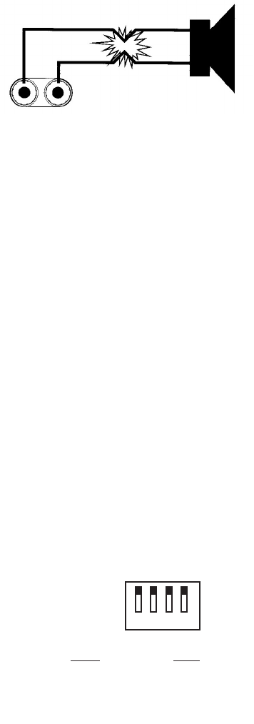
during the “Short Circuit Protection" will be interrupted (i.e. no sound output). Short Circuit Protection
can usually be traced back to the signal output line (i.e. speaker line). Check the line from the output
terminal of the amplifier to the speaker. If this line good, check the internal speaker connections and
components. A short circuit will usually be traced to a bad cable or a bad speaker component and is
rarely traced to the amplifier itself.
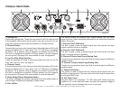
Thermal Protection - A single variable-speed fan on the V1000plus and dual variable speed fans on the V2000plus and V3000plus
amplifiers provide adequate cooling. During low level output the fans run at normal speeds. During high output and as heat raises,
(exceeding 90°C.), the fans will run at higher speeds to aid the cooling process. If the heatsink temperature exceeds 91°C., the ampli-
fier will mute until the amplifier cools down. When the amplifier cools below 90°C., the amplifier will return to normal operations. Be
sure not to operate your amplifier below the minimum load ratings to reduce the risk of overheating problems.
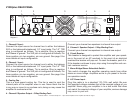
Input/Output Protection - The input circuits are isolated by 10k resistors. An ultrasonic network uncouples RF from the output and
helps keep the amplifier stable with reactive loads.
Operating Voltage (AC Mains) - The serial number label indicates the correct AC main voltage. Connecting to the wrong voltage is
dangerous and may damage the amplifier. Always be sure the source voltage for your areas matches the required voltage for your
amplifier.
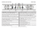
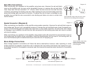
Gain Controls - The gain controls are located on the front panel and are calibrated in 2dB of attenuation from full gain. It is best to
adjust the amplifier so no “hissing” is heard from speakers with no music being played, this will ensure the lowest possible distortion
during normal operation.
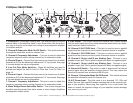
Low Cut Filter (V2000 and V3000 Only) - The low-cut filter removes extremely low frequencies from the audio signal that could cause
speaker distortion or damage. The dip switches on the rear panel allows you to enable or disable the filter for each channel, as well as
adjust either a 50Hz or 30 Hz cut-off. Always use the 50 Hz filter setting if you are using the amplifier to drive a distributed line system
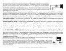
(also known as a constant-voltage line, 70 volt line, etc.). The dip switches on the rear panel allows you to configure the low cut filter.
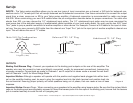
The diagram below detail the functions of each dip switch, the functions are also printed on the rear panel of the amplifier.
CH. 1 CH.2
1 Low Cut 3 ON=30Hz
On/Off OFF=50Hz
2 ON=30Hz 4 Low Cut
OFF=50Hz On/Off
1
2 3
4
OFF
ON
Configuring the Low Cut Filter:
Activating Low Cut Filters - Dip switches 1 and 4 activate and deactivate the Low Cut Filter. Channel 1 filters is
control by dip switch 1 and channel 2 filter is controlled by dip switch 4.
Low Cut Frequency Selector - When the Low Cut Filter is activated, dip switches 2 (channel 1) and 3 (channel
2) will control the frequency roll-off. When dip switches 2 and 3 are in the "ON" the filter will cut off frequencies
at and below 30Hz, when these dip switches are in the "OFF" position the filter will cut off frequencies at and
below 50Hz. Please note: Each channel operates independently of each other allowing each channel to have
different filter settings.
American Audio® - www.americandj.com - Vplus Series Amplifiers Power Amplifier User Manual Page 14