


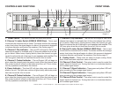
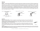
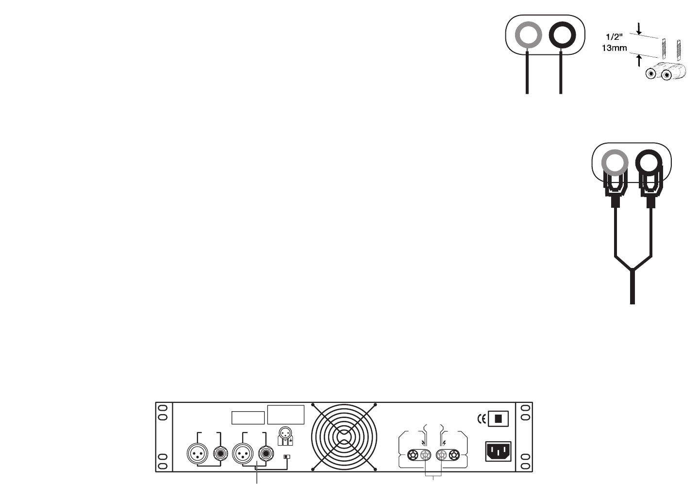
Bare Wire Connections:
When connecting your speakers to the amplifier using bare wire; Unscrew the red and black
caps on the binding post, be sure not to completely remove or unscrew the red and black
caps. Strip back the wire insulation 1/2” (13mm). Insert the bare wire into the hole that was
reveled by unscrewing the binding post cap. After inserting the wire into the binding post hole,
screw the binding post cap down on the wire. To reduce the risk of shock or damage to your
amplifier, be sure that the wire connected to one binding post does not come in contact with
that of another.
Spade Connector: (Diagram 6)
When connecting your speakers to the amplifier using spade connector; Unscrew the red and black caps on
the binding post, be sure not to completely remove or unscrew the red and black caps. Insert the spade con-
nector in to the binding post and tighten the caps down on the spade connector. To reduce the risk of shock
or damage to your amplifier, be sure that the wire connected to one binding post does not come in contact
with that of another.
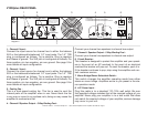
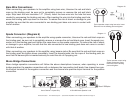
When connecting your speakers to the amplifier using banana jacks; Be sure that the red and black caps on
the binding post are tighten down completely. Insert the banana jacks into the caps of the binding post, be
sure that the banana jack is inserted securely to avoid the risk of it popping out.
Mono Bridge Connections:
Mono bridge operation connections will follow the above descriptions however, when operating in mono
bridge operation the speaker connections will run between the two positive (red) leads. Use channel two pos-
itive output terminal for the negative connection and the channel one positive output terminal for the positive
connection.
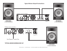
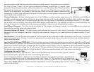
Typical speaker output using bare wire. Insert
bare wire into the binding post and tighten.
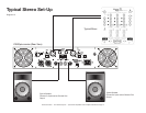
Typical speaker output using
spade connectors. Insert
bare wire into the binding
post and tighten.
Diagram 11
Diagram 10
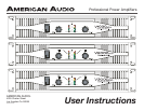
1000 W
ATTS
BRIDGE
MONO
120V~60Hz
6
A
M
P
CAUTION
4 OHMS MINIMUM IMPEDANCE PRE CHANNEL
4 OHMS MINIMUM IMPEDANCE IN MONO BRIDGE MODE
OUTPUT
INPUT
CH 1
WARNING: TO REDUCE THE
RISK OF FIRE OR ELECTRICAL
SHOCK DO NOT
EXPOSE THIS
EQUIPMENT TO RAIN OF MOIS-
TURE
AVIS: RISQUE DE CHOC ELECT
-
TRIQUE - NE PAS OUVRIR.
P2P3P1
+
- +
-
+
-
+
CH 1CH 2
PROFESSIONAL
POWER AMPLIFIER
STEREO BRIDGE
INPUT
CH 2
X
X
4 Ohm Minimum Speaker Load
Uses Channel 1 Inputs Only
Rear V1000
plus
American Audio
®
- www.americandj.com - V
plus
Series Amplifiers Power Amplifier User Manual Page 10
Diagram 12