


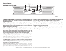
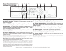
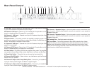
OUTPUTS:
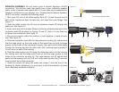
Binding Post/Banana Plug - Connect your speakers to the binding post outputs on the rear of the amplifier. The
speaker wire may be connect by bare wire (directly connected, usually for permanent connections), banana plug,
or spade connector. Connections are made to Channels 1 and 2 output’s for stereo mode or across the red ter
-
minals of Channels 1 and 2 for Mono Bridge Mode.
Important Notice: Although a speaker will operate with the positive and negative leads plugged into either ter
-
minal on the amplifier binding post, be sure to plug the negative lead into the black terminal and positive lead
into the red terminal. Ensuring proper polarity
will avoid speakers being out of phase, that can cause a loss of
bass response.
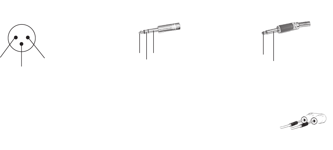
Important Notice: Banana Plugs - When connecting your speakers to the amplifier using banana jacks; Be sure that the red and black
caps on the binding post are completely screwed in. Insert the banana jacks into the caps of the binding post, be sure that the banana
jack is inserted securely to avoid the risk of it popping out.
Figure 8
©American Audio® - www.americanaudio.com - VLP Series™ Power Amplifier User Manual Page 9
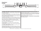
Set Up
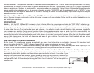
INPUTS - The VLP Series amplifier allows you to use two types of input connector per a channel, a XLR jack for balanced connections
and a 1/4” female jack that will accept balanced and unbalanced connectors. Use these connections to connect the output signal from
a mixer, cross-over or EQ to your VLP S
eries amplifier. A balanced connection is recommended for cable runs longer that 20ft. When
constructing your own XLR cables follow the pin configuration describe below for proper connections. For cable runs shorter than
20ft. you may choose the 1/4” unbalanced input option. The 1/4” unbalanced input option may be more convenient for most users
due to the abundant supply of prefabricated cables available at your local audio dealer. You may use the two XLR “Input Thru” jacks
to jump a parallel connection to another amplifier or other device. For Example: Connect a XLR cable to the input of channel one. You
may now connect a XLR cable from the channel one “Input Thru” jack to the input jack of another amplifier’s channel one input. This
will reduce the use of “Y” cables.
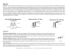
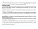
Unbalanced TS 1/4” Plug
Hot (+)
Negative (-)
Figure 7
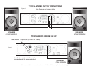
Balanced TRS 1/4” Plug
Ground/Shield
Hot (+)
Negative (-)
Figure 6
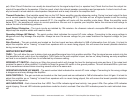
2 Hot (+ data)
3 Negative (- data)
1 Ground/Return/ 0v)
1
3
2
Male XLR Pin Confi guration:
US ITT Standard
Figure 5