


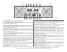
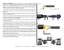
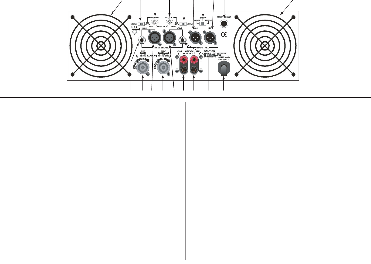
13. Cooling Fans - Dual high speed cooling fans
14. Channel 2 Subwoofer Mode On/Off Switch - Turns the subwoofer
mode for channel two on and off.
15. Channel 2 Frequency Adjustment - This knob is used to adjust the
frequency level sent to your speaker on channel two when running the
channel in subwoofer mode.
16. Channel 1 Frequency Adjustment - This knob is used to adjust the
frequency level sent to your speaker on channel one when running the
channel in subwoofer mode.
17. Channel 1 Subwoofer Mode On/Off Switch - Turns the subwoofer
mode for channel one on and off.
18. Channel 2 XLR THRU Jack - This jack is used to send a parallel
signal from the channel two input jacks to another device or amplifier.
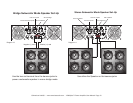
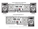
19. Mode Switch - This switch controls the amplier’s operating mode.
The amplier can operate in three different modes; Mono Bridge, Parallel
Mono, or Stereo. The amplier is shipped in stereo mode.
20. Channel 1 XLR THRU Jack - This jack is used to send a parallel
signal from the channel one input jacks to another device or amplifier.
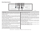
21. Reset Button - This button is used to reset the breaker.
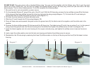
22. AC Cord - Plug this cable into a standard 110~120v wall outlet.
Check that the voltage in your area matches the ampliers required volt-
age. To get optimum power out of this particular amplier, switch the
standard Edison plug to a 30 amp. plug. (See page 15)
23. Channel 1 TRS Input - Channel one 1/4” female jack. Excepts either
a balanced or unbalanced plug. See page 7 for more details.
24. Channel 1 Output Jack/5 way Binding Post - Connect to your
speaker’s input jack. Red is positive signal and Black is negative signal.
25. Channel 2 Output Jack/5 way Binding Post - Connect to your
speaker’s input jack. Red is positive signal and Black is negative signal.
26. Channel 1 XLR input - Channel one 3-pin XLR balanced input jack.
See page 7 for more details.
27. Channel 1 Speakon Output - Optional speaker output connections.
Use pins 1+ and 1- of this 4-pole Speakon connector to connect to your
speaker’s Speakon input jack.
28. Channel 2 XLR Input - Channel two 3-pin XLR balanced input jack.
See page 7 for more details.
29. Channel 2 Speakon Output - Optional speaker output connections.
Use pins 1+ and 1- of this 4-pole Speakon connector to connect to your
speaker’s Speakon input jack.
30. Channel 2 TRS Input - Channel two 1/4” female jack. Excepts either
a balanced or unbalanced plug. See page 7 for more details.
Diagram 2
13 1320191817161514
23 22
21
29 28 27 26 25 2430
©American Audio® - www.americanaudio.com - V5000plus™ Power Amplifier User Manual Page 6