


©American Audio® - www.americanaudio.com - V5000plus™ Power Amplifier User Manual Page 12
put). Short Circuit Protection can usually be traced back to the signal output line (i.e. speaker line). Check the line from the output ter-
minal of the amplifier to the speaker. If this line good, check the internal speaker connections and components. A short circuit will usu-
ally be traced to a bad cable or a bad speaker component and is rarely traced to the amplifier itself.
Thermal Protection - Dual variable speed fans on the V5000plus amplifier provide adequate cooling. During low level output the fans
run at normal speeds. During high output and as heat raises, (exceeding 90°C.), the fans will run at higher speeds to aid the cooling
process. If the heatsink temperature exceeds 91°C., the amplifier will mute until the amplifier cools down. When the amplifier cools
below 90°C., the amplifier will return to normal operations. Be sure not to operate your amplifier below the minimum load ratings to
reduce the risk of overheating problems.
Input/Output Protection - The input circuits are isolated by 10k resistors. An ultrasonic network uncouples RF from the output and
helps keep the amplifier stable with reactive loads.
Operating Voltage (AC Mains) - The serial number label indicates the correct AC main voltage. Connecting to the wrong voltage is
dangerous and may damage the amplifier. Always be sure the source voltage for your areas matches the required voltage for your
amplifier.
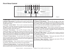
Gain Controls - The gain controls are located on the front panel and are calibrated in 2dB of attenuation from full gain. It is best to
adjust the amplifier so no “hissing” is heard from speakers with no music being played, this will ensure the lowest possible distortion
during normal operation.
AMPLIFIER FEATURES:
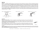
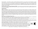
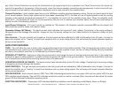
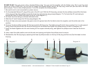
THRU - Thru will allow the user to daisy-chain one amplifiers signal input into another amplifier. Plug the signal source outputs into the
first amplifier’s input, patch from the amplifier’s THRU jacks to the next amplifier’s input, and so on, daisy-chaining as many amplifiers
as there is no excessive level loss. Is not affected by crossover setting.
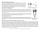
GROUND LIFT SWITCH - Applying or lifting the ground switch will change the level for background noise and hum, if the noise level
remains the same in either position, it is better to keep the ground lift switch in the ground position. This will eliminate 60Hz cycle hum
that is sometimes induced when mounting several units in the same rack.
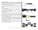
OPERATING VOLTAGE (AC MAINS) - The serial number label indicates the correct AC main voltage. Connecting to the wrong voltage
is dangerous and may damage the amplifier.
GAIN CONTROLS - The gain controls are located on the front panel and are calibrated in 2dB of attenuation from full gain. It is best to
adjust the amplifier so no “hissing” is heard from speakers with no music being played, this will ensure the lowest possible distortion
during normal operation.
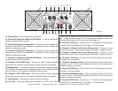
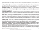
LED INDICATORS - Each channel has six LEDS. Four LEDs indicate signal level activity; two green LED and two yellow LED. One red
LED indicates signal clipping. One red LED indicates protections mode for shorts/ overload. Both channels will also share the center
green LED that indicate the amplifier operating mode.
FUNCTION INDICATORS - These green LED indicators detail the amplifiers current operating mode (Stereo, Mono, or Bridge).