


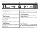
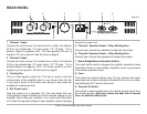
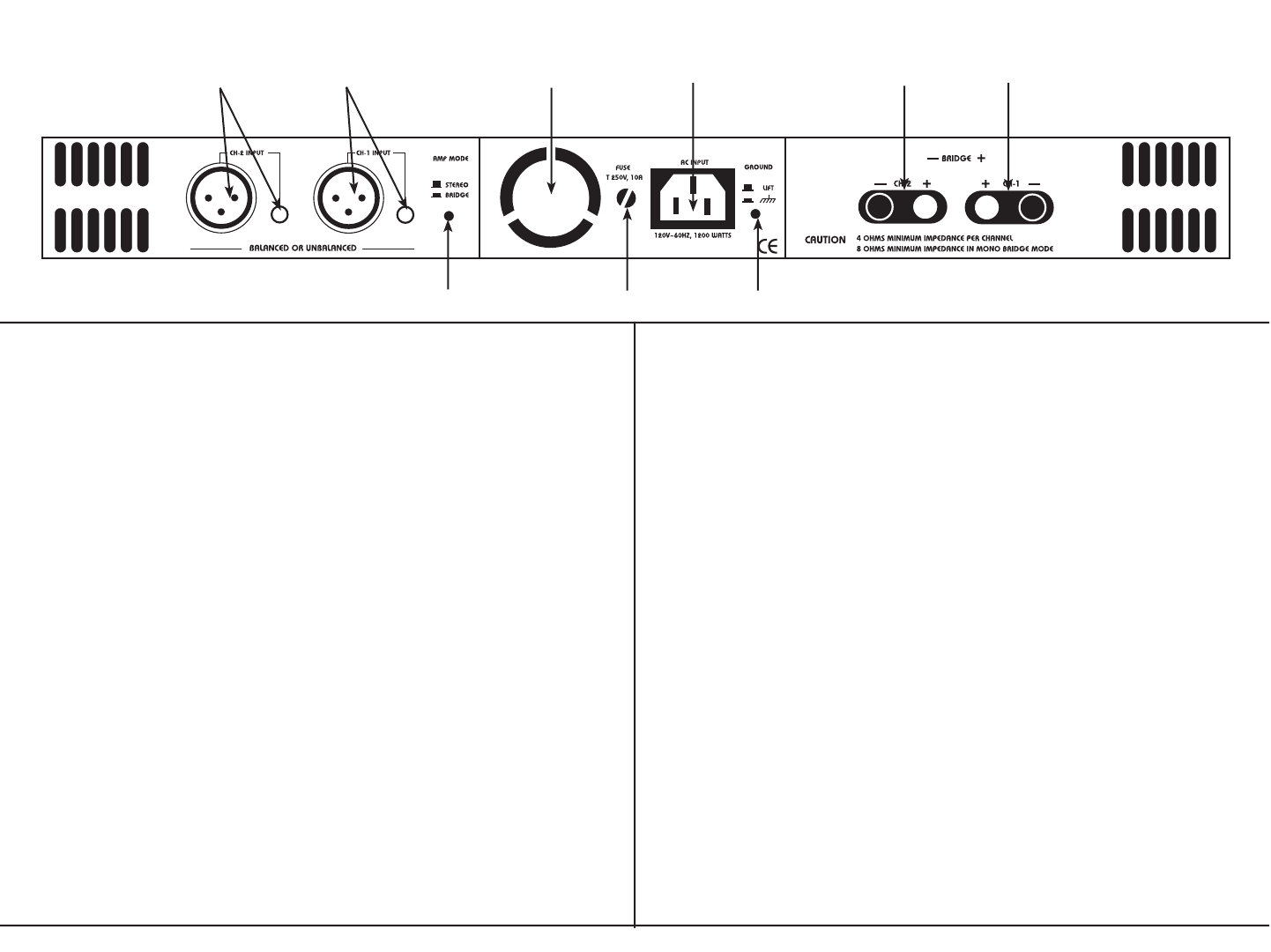
REAR PANEL
654321
7 8 9
1. Channel 1 Input -
Connect the input source for channel one to either the balance
XLR or the unbalanced 1/4” input jacks. 1/4” TS plug - Tip is
positive, Sleeve is negative. XLR - Pin three positive, Pin two is
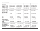
negative, Pin one is ground. See the chart on page 6.
2. Channel 2 Input -
Connect the input source for channel two to either the balance
XLR or the unbalanced 1/4” input jacks. 1/4” TS plug - Tip is
positive/Sleeve is negative. XLR - Pin three positive, pin two
negative, pin one ground. See the chart on page 6.
3. Cooling Fan -
This is a dual speed cooling fan. This fan is used to cool the
internal parts of the amplifier when in use. Never block the fan
in any way or mount in an enclose rack, doing so may cause the
amplifier to overheat and fail.
4. A/C Power Input -
Plug this cable in to a standard 110~120v wall outlet. Be sure
that supplied voltage matches that of the required voltage of you
amplifier. Never plug your amplifier in to a wall outlet that does
not match the required voltage of your amplifier, serious damage
may occur to your unit.
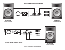
5. Channel 1 Speaker Output - 5 Way Binding Post -
Connect your channel one speakers to channel one output.
6. Channel 2 Speaker Output - 5 Way Binding Post -
Connect your channel two speakers to channel two output.
7. Mono-Bridge/Stereo Selectable Switch -
This push button switch changes the amplifier operating mode
from either stereo or mono bridge. Amplifiers arrive to you preset
in the stereo operation mode.
8. Fuse -
This house the external 8amp fuse. All way replace with exact
same type fuse unless otherwise instructed to do so by an autho-
rized American DJ™ service technician.
9. Ground Lift Switch -
This switch is used to disconnect the internal ground signal from
the chassis ground. This may reduce the buzz that is caused
from an electrical 60Hz cycle.
V1500™ Power Amplifier Instructions page 5
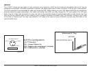
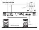
Diagram 2