


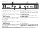
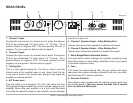
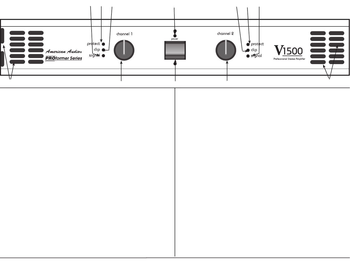
FRONT PANEL
1. Channel 1 Signal indicator -
This Green LED will glow when there is an input signal present.
2. Channel 1 Protect indicator -
This red LED will glow when channel one goes in to protect mode.
In protect mode the output signal to the speakers will terminated
to channel one.
3. Channel 1 Clip indicator -
This LED comes on at the amplifiers clipping point, the point when
the output signal begins to distort. Under heavy clipping lower
the input gains (Diagram 8) to reduce the risk of damage to your
speakers and amplifier.
4. Power LED -
This LED will glow when the amplifier is turned on, indicating
power is going to the unit.
5. Channel 2 Clip indicator -
This LED comes on at the amplifiers clipping point, the point when
the output signal begins to distort. Under heavy clipping lower the
input gains (Diagram 10) to reduce the risk of damage to your
speakers and amplifier.
8
2 3
10
1
4 6
9
V1500™ Power Amplifier Instructions page 4
5 7
6. Channel 2 Protect indicator -
This red LED will glow when channel two goes in to protect mode.
In protect mode the output signal to the speakers will terminated
to channel two.
7. Channel 2 Signal indicator -
This Green LED will glow when there is an input signal present.
8. Channel 1 Gain control -
This knob adjust the channel one volume output to the speakers
connect to channel one.
9. Power Switch -
This switch turns the unit on.
10. Channel 2 Gain control -
This knob adjust the channel one volume output to the speakers
connect to channel one.
11. Exhaust Cooling Vents -
A cooling fan is mounted at rear of the amplifier. These exhaust
vents allow hot air to be pushed out of the amplified to allow
ample cooling of the internal components. Do Not Block These
Vents!
11
11
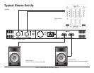
Diagram 1