


16
32
28
15
29
27
33
26
25
24
23
22
20
21
18
19
17
15
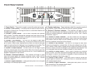
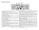
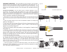
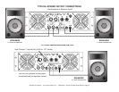
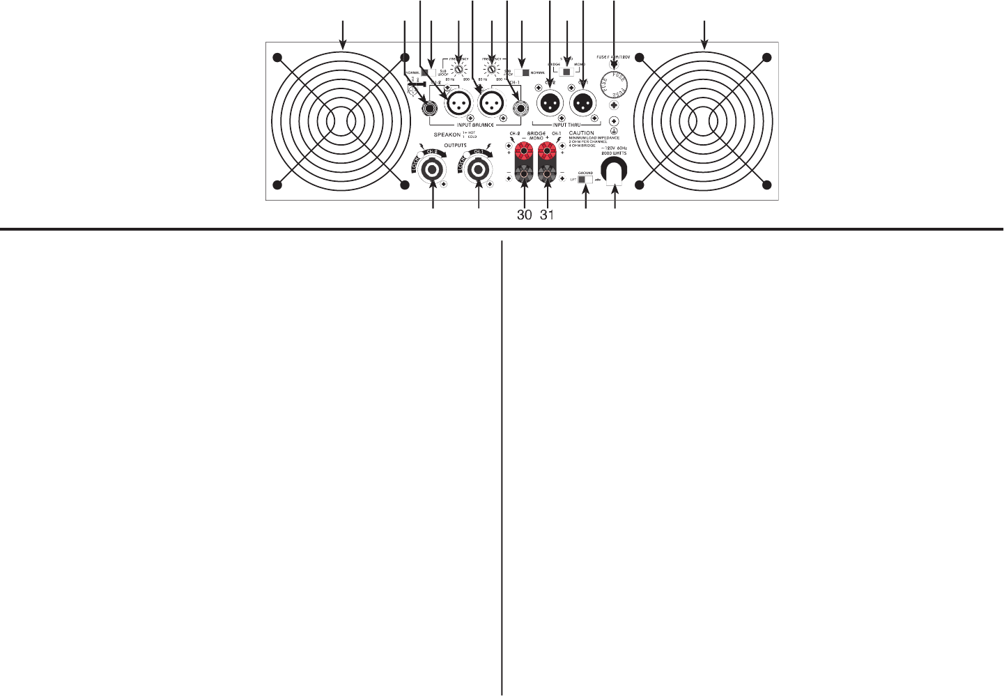
Rear Panel Control
15. Cooling Fans -
Dual high speed cooling fans
16. Channel 2 TRS Input -
Channel two 1/4” female jack. Excepts ei-
ther a balanced or unbalanced plug. See page 7 for more details.
17. Channel 2 XLR Input -
Channel two 3-pin XLR balanced input jack.
See page 7 for more details.
18. Channel 2 Subwoofer Mode On/Off Switch -
Turns the subwoofer
mode for channel two on and off.
19. Channel 2 Frequency Adjustment -
This knob is used to adjust the
frequency level sent to your speaker on channel two when running the
channel in subwoofer mode.
20. Channel 1 XLR input -
Channel one 3-pin XLR balanced input jack.
See page 7 for more details.
21. Channel 1 Frequency Adjustment -
This knob is used to adjust the
frequency level sent to your speaker on channel one when running the
channel in subwoofer mode.
22. Channel 1 TRS Input -
Channel one 1/4” female jack. Excepts ei-
ther a balanced or unbalanced plug. See page 7 for more details.
23. Channel 1 Subwoofer Mode On/Off Switch -
Turns the subwoofer
mode for channel one on and off.
24. Channel 2 XLR THRU Jack -
This jack is used to send a parallel
signal from the channel two input jacks to another device or amplifier.
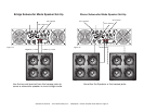
25. Mode Switch -
This switch controls the ampli er’s operating mode.
The ampli er can operate in three different modes; Mono Bridge, Parallel
Mono, or Stereo. The ampli er is shipped in stereo mode.
26. Channel 1 XLR THRU Jack -
This jack is used to send a parallel
signal from the channel one input jacks to another device or amplifier.
27. Fuse Holder -
This holder houses the external 20 amp fuse. Always
replace with the exact same type fuse unless otherwise instructed to do
so by an authorized American Audio
®
service technician.
28. Channel 2 Speakon Output -
Optional speaker output connections.
Use pins 1+ and 1- of this 4-pole Speakon connector to connect to your
speaker’s Speakon input jack.
29. Channel 1 Speakon Output -
Optional speaker output connections.
Use pins 1+ and 1- of this 4-pole Speakon connector to connect to your
speaker’s Speakon input jack.
30. Channel 2 Output Jack/5 way Binding Post -
Connect to your
speaker’s input jack. Red is positive signal and Black is negative signal.
31. Channel 1 Output Jack/5 way Binding Post -
Connect to your
speaker’s input jack. Red is positive signal and Black is negative signal.
32. Ground Lift Switch -
This switch is used to disconnect the internal
ground signal from the ampli er’s chassis ground. This may reduce the
buzz that is sometimes caused from an electrical 60Hz cycle.
33. AC Cord -
Plug this cable into a standard 110~120v wall outlet. Be
sure that the supplied voltage in your area matches the ampli ers re-
quired voltage.
Diagram 2
©American Audio® - www.americandj.com - V4000plus™ Power Amplifier User Manual Page 6