


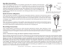
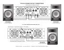
OVERHEAT INDICATOR -
Two red LED’s for this function, one for each
channel. When the amplifier’s heat sink temperature rises above 91° C.,
output will be discontinue and the red overheat LED glow continuously. One
channel can still operate normally if the other goes into overheat protection
mode.
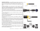
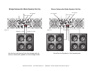
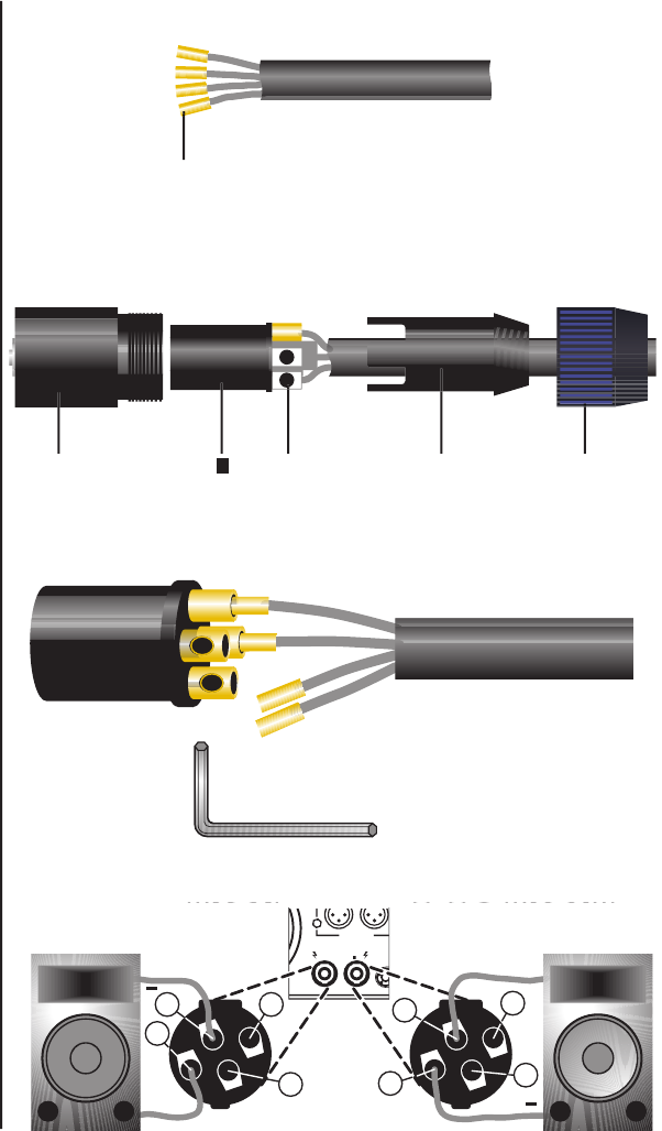
SPEAKON ASSEMBLY:
You will need a pair of Neutrik Speakon
®
NL4FC
connectors. You will also need high-quality two or four conductor speaker
cable, a pair of needle-nosed pliers and a 1.5-mm Allen key to assemble the
Speakon connectors to your speaker wire. To assemble the Neutrik Speakon
NL4FC connector, complete the following steps:
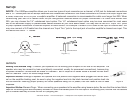
1. Strip back 3 /4-inch of the cable casing. Strip off 1 /4-inch from the end of
each of the conductors down to bare wire, and insert the brass ttings ( Figure
10).
2. Slide the cable tension clip (D) and the speakon coupler (E) through the
cable end. See gure 11.
3. Insert each wire with the brass ttings into the top of appropriate slot of the
connector insert (B) as shown in gures 11 and 12. Use a 1.5-mm Allen key to
tighten the connection (Figure 12).
4. Be sure to properly match the positive (+) and negative (–) leads of each
wire (Figure 13).
5. Slide the connector insert (B) into the connector housing (A), making sure
that the large notch on the outer edge of the insert lines up with the large
groove on the inside of the connector housing. The insert should slide easily
through the housing and out the other side until it extends approximately 3
/4-inch from the end of the housing.
6. Slide the cable tension clip (D) along the cable and insert into the housing
(A), making sure that the large notch lines up with the large groove on the
inside of the connector housing (A). The cable tension clip (D) should slide
easily into the housing until only 3 /8-inch of the cable tension clip (D) extends
from the back end of the connector.
7. Slide the coupler (E) along the cable and screw it onto the end of the
housing (A). Before tightening, you may want to test the connector to make
sure it has been assembled properly.
Figure 10
C
1
C
2
UTPUT
S
INPUT BA
ANCE
SPEAKON
1+ HO
T
1
COL
D
- +
+
+1
+1
+1
-1
+2
+2
+2
+2
+2
+
+1
+1
-1
+2
+2
+2
+2
Figure 13
Figure 12
4-Conductor Speaker Cable
Brass Inserts
Figure 11
D E
A C
BA CB
©American Audio® - www.americandj.com - V4000plus™ Power Amplifier User Manual Page 12