


V2000
plus
V2000plus V2000
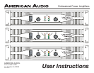
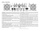
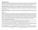
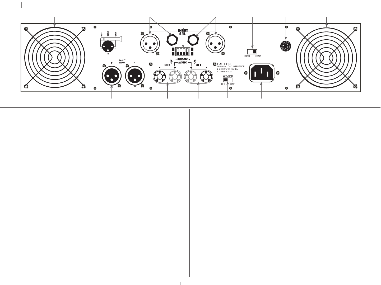
REAR PANEL
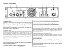
1. Cooling Fan -
Dual speed cooling fans. These fans are used to cool the internal parts
of the amplifier. Never block the fan grills in any way or mount in an en-
close rack, doing so may cause the amplifier to overheat and fail.
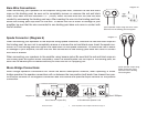
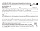
2. Channel 2 Input -
Connect the input source for channel two to either the balance XLR or the
balanced/unbalanced 1/4” input jacks. The 1/4” TRS plug is configured
as follows; Tip is positive, Ring is negative and Sleeve is ground. The
XLR jack is configured as follows; Pin three positive, pin two negative,
pin one ground. See page 9 for more details on input configuration.
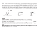
3. Low Cut Filter Mode Switches -
These dip switches are used to active and adjust the built-in Low Cut
Filter, see "Low Cut Filter" on page 14.
4. Channel 1 Input -
Connect the input source for channel one to either the balance XLR or the
balanced/unbalanced 1/4” input jacks. The 1/4” TRS plug is configured
as follows; Tip is positive, Ring is negative and Sleeve is ground. The
XLR jack is configured as follows; Pin three positive, pin two negative,
pin one ground. See page 9 for more details on input configuration.
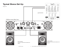
5. Mono-Bridge/Stereo Selectable Switch -
This switch changes the amplifier operating mode from either stereo or
mono bridge. Amplifiers are shipped in stereo mode.
6. Fuse Holder -
This holder houses the external fuse. Always replace with the exact
same type fuse unless otherwise instructed by an authorized American
Audio
®
technician.
7. Channel 2 XLR THRU Jack -
This jack is used to send a parallel signal from the channel two input
jacks to another device or amplifier.
8. Channel 1 XLR THRU Jack -
This jack is used to send a parallel signal from the channel one input
jacks to another device or amplifier.
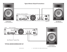
9. Channel 2 Output Jack/5 way Binding Post -
Connect to your
speaker’s input jack. Red is positive signal and Black is
negative signal.
10. Channel 1 Output Jack/5 way Binding Post -
Connect to your
speaker’s input jack. Red is positive signal and Black is
negative signal.
11. Ground Lift Switch -
This switch is used to disconnect the internal ground signal from the
amplifier chassis ground. This may reduce the buzz that is caused from
an electrical 60Hz cycle.
12. A/C Power Input -
Plug this cable in to a standard 110~120v wall outlet. Never plug your
amplifier in to a wall outlet that does not match the required voltage of
your amplifier, serious damage may occur to your unit.
your amplifier, serious damage may occur to your unit.
Diagram 3
1
2
3
4
3
1
4
10
9
8
7
2
11
12
5
1
6
American Audio
®
- www.americandj.com - V
plus
- www.americandj.com - Vplus - www.americandj.com - V
Series Amplifiers Power Amplifier User Manual Page 7