OPERATING MODES:
Stereo Operation -
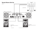
Page 10/Figure 9 details an example of a typical stereo set-up. Connect your inputs into channels one and two of
the amplifier. Connect your speakers to the outputs on the rear of the amplifier. Be sure that your front gain controls are turned down
to their lowest level (full counter-clockwise). Turn your amp on. Turn your input source level up. Use your front gain controls to regu-
late the output volume. Be sure not to raise the volume to the clip level, however an intermittent clip signal is acceptable.
Mono Bridge Operation -
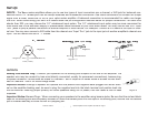
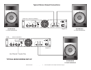
Page 9/Figure 8 details a mono bridge set-up. Be sure your amplifier and all other audio equipment is pow-
ered down. Flip the Stereo/Mono Bridge switch to the Mono Bridge position. Connect an input signal to channel one. Connect your
speaker across the red output binding post on the rear of your amplifier. Turn your equipment on (your amplifier should always be the
last item you turn on). Apply an input source signal to your amplifier. Turn channel two gain up. Use the channel one gain to regulate
your amplifier output.
Bridged-Mono Mode Caution -
The voltage across the output terminals of a bridged V
plus
The voltage across the output terminals of a bridged Vplus The voltage across the output terminals of a bridged V
series amplifier may equal or exceed 100
volts RMS and may be as high as 130 volts. Use fully insulated CLASS ONE wiring, and the load must be rated for up to 2500 watts
(@4 ohms)
PROTECTION:
LIMITER -
The Vplus series comes with a built in limiter. When the input signal overloads, the “CLIP LED’s” indicate a signal overload,
at this time, the master volume should be lowered to reduce distortion. If the input gain level is not reduced the built-in limiter will acti-
vate. During signal overload, the limiter will reduce the input audio signal enough to minimize the amount of clipping. A limiter takes
the gain of an overloading signal and reduces it, the reduction in gain reduces distortion that can cause damage to your speakers and
amplifier. During normal operation below clipping, and momentary clips on peaks, the limiter does not affect the audio signal and is
inaudible. It will allow brief clipping of peaks and will only activate when continuous, hard clipping occurs. During excessive clipping
the limiter will reduce the audio signal enough to minimize the amount of clipping. When the input signal decreases enough that clip-
ping ends, the limiter will deactivate and cease its gain reduction. The limiter has a fixed threshold and can not be adjusted.
Safe Power Levels at Different Output Loads:
8-Ohm Loads:
The amplifier can operate at practically any power level without risk of overheating. However, if it is pushed hard
enough to continually light the “CLIP ” indicator, the amplifier’s average output power can reach 150 watts.
4-Ohm Loads:
If the “CLIP ” indicator flashes occasionally, the amplifier is approaching its maximum long-term power capacity. If it is
lit about half the time, the amplifier channel will probably go into thermal protection within a few minutes.
2-Ohm Loads:
Except for an occasional flash, keep the “CLIP ” indicator dark to avoid overheating the amplifier channel. Clipping
should be kept to a reasonable minimum. An amplifier’s peak current draw at full output power into 2 ohms is several times what the
“normal ” draw is, but its various protection circuits will prevent this condition lasting more than a minute or two.
Short Circuit Protection -
The V
plus
The VplusThe V
series amplifiers all come with built-in Output Short Circuit Protects. The Output Short Circuit
Protection protects the output devices of the amplifier from short circuits and stressful loads. If your speaker lines short, the ampli-
fier automatically detects this problem and discontinues operation for that channel. If one side of your amplifier becomes shorted and
American Audio
®
- www.americandj.com - V
plus
- www.americandj.com - Vplus - www.americandj.com - V
Series Amplifiers Power Amplifier User Manual Page 13


