


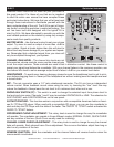
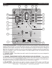
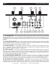

Q-D5™ Controls and Features Cont.
incoming signal to the headphones. The cue level is adjusted by the CUE LEVEL ADJUSTMENT KNOB
(13). Be sure the cue level is set to minimum before putting a pair of headphones on. Be sure the CUE
MIXING KNOB (12) is turned to the “CUE” position to hear the selected channel source.
5. TALKOVER BUTTON - When engaged this function will decrease all signal levels, except the
microphone level, by 15dB. A red LED next to the Talkover Button will glow when the talkover function
is engaged. In the OFF position all signals will remain at their normal levels.
6a. MICROPHONE VOLUME - This knob is used to regulate the microphone output volume. Turning
the knob in a clockwise direction will increase the volume level.
6b. MICROPHONE EQ SECTION - These controls are used to adjust the microphone treble level,
midrange, and bass levels. Each microphone input has a separate channel EQ.
MICROPHONE TREBLE CONTROL - This knob is used to adjust the treble levels of the
Microphone with a maximum signal gain of 15dB or maximum signal decrease of -30dB.
Turning the knob in a counter-clockwise direction will decrease the amount of treble
applied to the microphone signal, turning the knob in a clockwise direction will increase
the amount of treble applied to microphone signal.
MICROPHONE BASS CONTROL - This knob is used to adjust the low frequency levels of
the microphone with a maximum signal gain of 15dB or maximum signal decrease of -30dB.
Turning the knob in a counter-clockwise direction will decrease the amount of bass applied to
the microphone signal, turning the knob in a clockwise direction will increase the amount
of bass applied to microphone signal.
7. CHANNEL CUT BUTTONS - These buttons are used to cut out the Treble, Mid or Bass frequencies
of the incoming audio signal. When these buttons are depressed the selected frequency level is cut by
100%. When a Cut Button is engaged a red LED located directly above the specific button will begin
to glow, indicating the cut function has been activated. Depressing the Cut Button will disengage the
cut function.
8. LEVEL INDICATORS - The dual LED’s indicators are used to indicate either the master output level
or the PFL level’s of channels one and two. The level indicators will directly reflect the operating mode
of the dB SELECTOR SWITCH (15).
9. CHANNEL GAIN CONTROL - This adjustment is used to adjust an audio source signal input gain
for a channel. Never use the gain control to adjust output volume. Setting the gain level properly will
ensure a clean output signal. To properly set the gain level controls:
1. Be sure the MASTER VOLUME CONTROL (11) is set to minimum (zero output).
2. Set the CHANNEL FADER (2) to level 7.
3. Begin play on an audio source connected to the channel you are adjusting.
4. Be sure the LED LEVEL INDICATOR FUNCTION SWITCH (15) is set to the PFL CH1/CH2
position.
5. Turn the PFL (4) function on, for the channel you are adjusting.
6. Use the GAIN CONTROL (9) to achieve an average output level of +4 dB.
10. MAIN POWER SWITCH - This is the main power ON/OFF button. The power switch will glow blue
when power is ON. Before main power is applied, be sure you have made all connections to the mixer.
Also be sure your amplifier(s) is(are) tuned off. Remember to avoid damaging pops, the mixer should
be powered on first and turned off last.
11. MASTER VOLUME CONTROL - This rotary knob is used to control the master output level (volume).
To avoid distorted output try to maintain an average output signal level +4 dB. Be sure this volume
©American Audio® - www.AmericanAudio.us - Q-D5™ Instruction Manual Page 6