


44
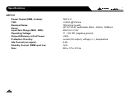
Fuse
55
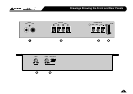
Input Gain Control
Use this control to match the pre-amp output level of your car audio source unit (tape or CD player) to the input stage of
the ADP amplifier. The amplifier's input gain is variable from 400mV (MAX Gain) to over 15V (MIN Gain).
Here are two different ways of setting up the input gain:
The easy (but less accurate) way is to turn the gain control on your ADP amplifier fully counter-clockwise to its MIN
(minimum gain) position, and then turn the volume control on your CD player to about 75%. Now play some music
and increase the gain on the ADP amplifier towards MAX until you arrive at your maximum preferred listening level,
or when the speakers begin to sound stressed. At this point, either the signal is clipping (i.e. exceeding its maximum
level before distortion) or you have reached the mechanical limits of the speakers. So just back down the gain control
a little and you should be set.
LTO
LTO
TM
Installation & Setup Instructions
The better way is to use a sine wave test tone (you'll find these on several test CDs) and an oscilloscope to check what
is the maximum clean output level from the source unit (i.e. your CD player etc.). Use a tone that is appropriate for the
speaker driver you are testing. For example, 60Hz for subs, 1KHz for mids or 8KHz for tweeters, and about 1KHz for
full-range speakers and component kits. Connect your oscilloscope probes across the +/ - terminals of the speaker
connected to your amplifier. Be sure to set the scope's input to AC. You may need to use a resistive network to reduce
the level of the signal being fed to your scope. Start with the amp gain set to about 25% and the volume control on
your source unit set low, then gradually turn up the volume (on the source unit) using the appropriate test tone track.
6
The unit is protected by a panel-mounted fuse (standard automotive type). If it becomes necessary to replace the fuse,
use only the same type and value as originally fitted (25A or 30A fuse).
Use the correct size Allen Key to tighten the terminal screws. Before reconnecting power to the circuit, double check all
connections are correct and ensure there are no stray strands of wire which could touch the chassis of the ADP amplifier
or any of the other terminals.
The power-on LED next to the power input terminal block will light to show the unit is receiving power. This is a 2 colour
LED. Green means that all is working correctly. Red means there is a problem (low voltage, high temperature, short circuit
etc.).