


5
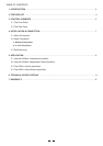
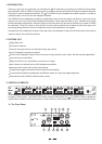
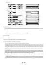
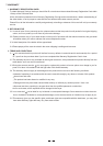
3.2 The Rear Panel
22
19
21
1820
17
16 15
14
PUSH
21
3
NEW TIDE
PUSH
21
3
NEW TIDE
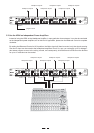
MAIN INPUT LEFT
MAIN INPUT RIGHTMAIN OUTPUT RIGHT MAIN OUTPUT LEFT
HEADPHONE OUT 6
HEADPHONE OUT 5
HEADPHONE OUT 4
HEADPHONE OUT 3
HEADPHONE OUT 2
HEADPHONE OUT 1
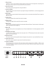
TIP:
L- CHANNEL
RING:
R- CHANNEL
MIN. LOAD
100OHMS
A101
AC INPUT
95-120V 60Hz
or 210-240V 50Hz
Rated Power
Consumption 40W
FUSE:
210-240V: T315mAL 250VAC
95-120V: 500mA 250VAC
REPLACE FUSE WITH
CORRECT TYPE ONLY
Apparaten skall anslutas
till jordat uttag nar den
ansluts till ett natverk
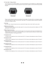
TIP/PIN2
RING/PIN3
SLEEVE/PIN1
TIP/PIN2
RING/PIN3
SLEEVE/PIN1
TIP/PIN2
RING/PIN3
SLEEVE/PIN1
TIP/PIN2
RING/PIN3
SLEEVE/PIN1
110-120V
220-240V
13
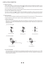
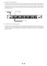
1. Direct In Input
Main Input on the rear panel, this input presents the priority character.
2. Input Gain Control
This control sets the input signal level coming from Main In.
3. Input Level Meter
-24dBu to +18dBu.
4. Aux In Input
Balanced Control.
5. L Mute Switch
The Left input signal will be muted if this switch is activated.
6. R Mute Switch
The Right input signal will be muted if this switch is activated.
7. Mode Switch
This push-button switches the operational mode between Mono and Stereo. Press this button for Mono appli-
cation, and the Mono LED (8) lights up.
8. Mono LED
lights up.
9. Headphone Out Output
signal of the individual channel.
10. Balanced Control
This control is used to set the proportion between the signal coming from Aux In Input and Main/Direct In Input.
11. Output Gain Control
This control is used to adjust the output level of the individual channel.
12. Output Level Meter
to avoid any distortion.
The Direct In Input is used to feed the external program sources into the main signal path, comparing to the
This meter tells you the level of the main input signal coming from Main/Direct In, and the range goes from
The Aux In Input is used to feed the further input signal, which can be mixed with the Main/ Direct In signal via
This LED informs you the current operational mode. Press the Mode Switch (7) for Mono application, this LED
In parallel with the Headphone Output on the rear panel, this 1/4" TRS phone jack is also used to output the
This 4-digit meter tells you the level of the output signal, and the range goes from -24dBu to +12dBu. In case
of the Clip LED lights up, please turn down the Input Gain Control or/and the individual Output Gain Control