


DISTRIBUTION AMPLIFIERS
5
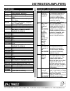
PIN No. Input signals on 15-pin D female
connector
12 Vertical Sync
13 Ground
14 Ground
15 Horizontal Sync
Table 4. The DA1406WM Input pin-out
PIN No. Output signals on 15-pin D female
connector
1 Ground
2 Red
3 Composite Sync
4 No connection
5 Green
6 Ground
7 No connection
8 No connection
9 Blue
10 No connection
11 Ground
12 Vertical Sync
13 Ground
14 Ground
15 Horizontal Sync
Table 5. The DA1406WM Outputs pin-out
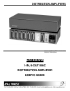
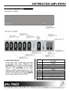
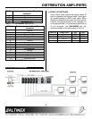
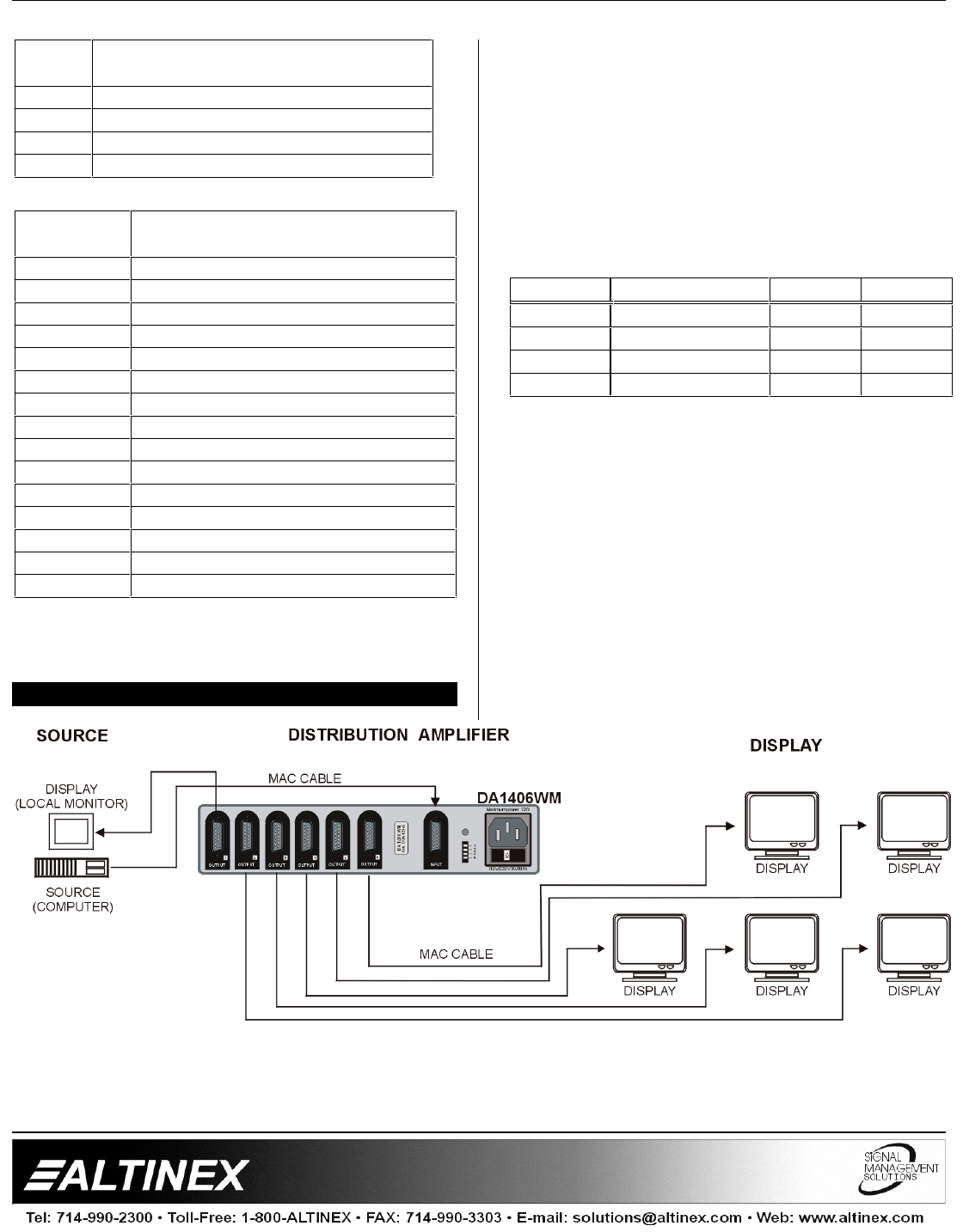
APPLICATION DIAGRAM 5
4.2 BOOT UP SWITCHES
Some Video cards require the proper sense ID
pins to determine the boot up mode. Sense pins
are usually present on MAC video cards. When
distribution amplifiers are used, the local monitor
(monitor connecting directly to the computer) is
no longer available. To insure the proper boot up
of the computer, the DA1406WM has dip-
switches located on the back panel of the unit.
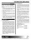
SWITCH FUNCTION ON OFF
1 Pin 4 GND OPEN
2 Pin 11 GND OPEN
3 Pin 12 GND OPEN
4 Not used
Table 6. Description dip-switches of the DA1406WM