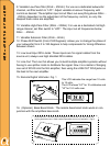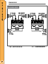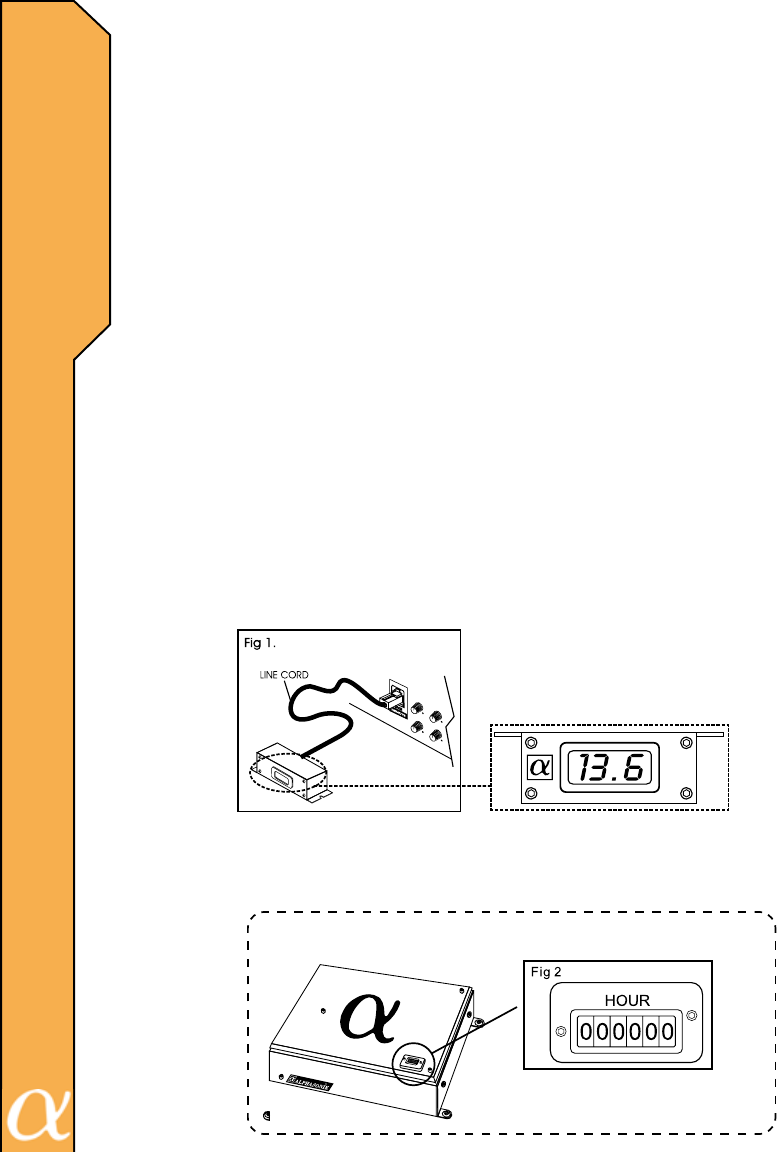
This LCD indicates the range from 10 volts
to 15 volts.
The LCD shows "LO" for 10 voltsbelow and
"HI" for 15.5 volts over.
HOUR METER - The hour meter is designed to provide the user with actual toal
running time for the unit. Each number represents one hour of operation. (Fig 2)
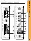
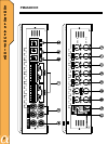
9. Variable Low-Pass lter (50Hz – 250Hz): For use as a dedicated subwoofer
channel, set lter switch to “LPF”. Adjust variable crossover frequency with
control as desired. The amplier input circuit lters out everything above 50Hz…
..250Hz (dependent on the adjustment of the frequency control), so only the
deepest bass notes are amplied.
10. Variable High-Pass Filter (50Hz – 250Hz): For use as a dedicated mid high
range channel, set lter switch to “HPF”. The input out all frequencies below
50Hz…..250Hz.
11. Variable Subsonic Filter (20Hz ~ 60Hz)
12. Phase Shift Switch (0 And 180 Degrees): allows you to change the phase of
your subwoofer from 0 to 180 degrees to help compensate for timing difference
between drivers
13. Low level Input RCA Jacks: These inputs are for signal cables from the
source unit, always use high shielded RCA cables.
14. Line Out: The Line Out allows you to build multiple amplier systems without
having to use splitter cords to distribute the signal. Now it is a matter of bringing
one set of RCA’S into the rst amplier, then using the LINE OUT RCA jacks as
the feed to the next amplier.
15. Remote Digital Voltmeter- Fig. 1
16. (Optional) Bass Boost Knob: The remote bass boost knob works in con-
junction with the ampliers bass knob.
9
C
O
N
T
R
O
L
S
&
F
U
N
C
T
I
O
N
S


