


© Copyright, Alliance Laundry Systems LLC – DO NOT COPY or TRANSMIT
Installation
202068
14
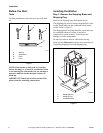
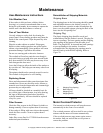
Additional Washer Security
(Coin Models Only)
Located on the service door of the washer is a flat
Phillips head screw. During shipment, this screw is
used to attach the service door to the meter case. For
additional security, this screw can be reinstalled inside
the control hood of your washer. Refer to instructions
below for installation.
Tamper-resistant screws also can be installed for
additional security. Tamper-resistant screws, bits and
bit holder are available as optional equipment at extra
cost. Part numbers are:
• Bit (No. 8 screws) Part No. 281P4
• Bit (No. 12 screws) Part No. 282P4
• Bit Holder (3/8 drive) Part No. 24161
• Control panel tamper-resistant screw
Part No. 35528
• Front panel tamper-resistant screw
Part No. 35527
The following list is the procedure required to install
the Phillips head screw and tamper-resistant screws:
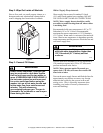
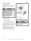
1. Remove the Phillips head screw from service
door (refer to Figure 14).
2. Remove two screws holding control panel to
control hood.
3. Tilt control panel forward and lay on a protective
pad to prevent scratching of cabinet top.
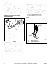
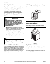
4. Insert Phillips head screw down through double
“D” hole in left rear corner of cabinet top (inside
control hood) until it engages retainer nut located
on left rear corner gusset of cabinet.
5. Finger tighten screw.
IMPORTANT: Do not use a power driver to tighten
screw. Torque of a power driver could over-tighten
screw causing damage to cabinet assembly.
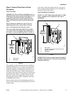
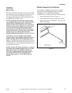
6. Secure control panel to control hood using two
No. 8 tamper-resistant screws, Part No. 35528.
7. Remove two screws holding front panel to base
of washer and install two No. 12 tamper-resistant
screws, Part No. 35527.
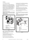
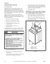
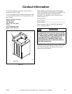
Figure 14
To reduce the risk of electric shock, fire,
explosion, serious injury or death:
• Disconnect electric power to the washer
before servicing.
• Never start the washer with any guards/
panels removed.
• Whenever ground wires are removed
during servicing, these ground wires
must be reconnected to ensure that the
washer is properly grounded.
W003
WARNING
Any disassembly requiring the use of tools
must be performed by a suitably qualified
service person.
W299
TLW2102N
1 35528 No. 8 Screws
2 Double “D” Hole
3 35527 No. 12 Screws
2
1
3