


© Copyright, Alliance Laundry Systems LLC – DO NOT COPY or TRANSMIT
Installation
202068
10
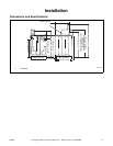
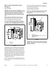
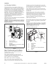
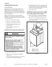
Low Standpipe Installation
If the drain facility is lower than the cabinet top, a
siphon break kit, Part No. 562P3, must be installed in
the drain hose to prevent siphoning action and drain
hose MUST be cut to fit the washer installation. Refer
to Figure 8. Use one No. 25863 Hose Coupling to
splice hose. The No. 562P3 Siphon Break Kit and No.
25863 Hose Coupling are available as optional
equipment at extra cost through an authorized dealer
or parts distributor. Installation instructions are
supplied with the kit.
OPTIONAL: Raise the standpipe to the recommended
height of 36 inches (91.44 cm).
IMPORTANT: Drain receptacle must be capable of
handling a minimum of 1-1/2 inch (3.8 cm) outside
diameter drain hose.
Figure 8
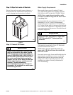
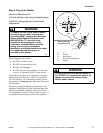
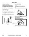
Step 5: Position and Level the Washer
Position washer so it has sufficient clearance for
installation and servicing.
Place washer in position on a clean, dry, and
reasonably firm floor. Installing the washer on any
type of carpeting is not recommended.
Place rubber cups on all four leveling legs.
Place a level on the cabinet top and check if the
washer is level from side to side and front to back.
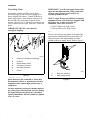
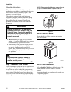
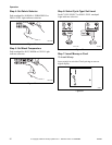
If washer is not level, tilt washer back to access the
front leveling legs. Loosen the locknuts and adjust legs
by screwing into or out of washer base.
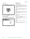
Once adjusted, tilt the washer forward on front legs
and lower back down into position to set the rear self-
leveling legs.
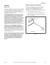
Washer must not rock. After washer is at desired
height, tighten locknuts securely against bottom of
washer base. If these locknuts are not tight, washer
will not remain stationary during operation.
Improper installation or flexing of weak floor will
cause excessive vibration.
Do not slide washer across floor once the leveling legs
have been extended, as legs and base could become
damaged.
NOTE: For areas with uneven floors, a No. 566P3
Adjustable Rear Leg Extension Kit is available as
optional equipment at extra cost.
Verify that unit does not rock.
Figure 9
W295I
1 Drain Hose Elbow
2 562P3 Siphon Break Kit
3 Standpipe
4 Cut Hose in This Area and Install No. 25863
Hose Coupling
5 25863 Hose Coupling
W295I
{
2
1
5
4
3
TLW2100N
1 Washer Base
2 Locknut
3 Leveling Leg
4 Rubber Cup
5 1/2 inch (12.7 mm) Clearance Between
Washers
6 Level
TLW2100N
1
3
2
5
4
6