


Installations
8 Matica 500/900 Reference Manual
Audio Installation: Input Wiring
SHOCK HAZARD – DO NOT OPEN
RISQUE DE CHOC ELECTRIQUE – NE PAS OUVRIR
TO PREVENT ELECTRICAL SHOCK DO NOT REMOVE COVERS.
NO USER SERVICEABLE PARTS INSIDE.
REFER SERVICING TO QUALIFIED SERVICE PERSONNEL.
TO REDUCE THE RISK OF FIRE OR ELECTRICAL SHOCK
DO NOT EXPOSE THIS EQUIPMENT TO RAIN OR MOISTURE.
MOUNT IN RACK ONLY. INSTALLER SUR SUPPORT DE MONTAGE SEULEMENT.
WARNING/AVIS:
´
ALESIS CORPORATION, LOS ANGELES
SOUND REINFORCEMENT DIVISION
Patent Pending
USE CLASS 2
WIRING
MATICA
MODEL
INPUT
POWER
OUTPUT
POWER
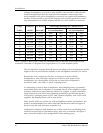
500
900
600 VA
1200 VA
250 W@4W
450 W@4W
MATICA POWER AMPLIFIER
™
DUAL
CHANNEL
AUDIO INPUT WIRING
=
=
=
TIP
RING
SLEEVE
=
=
=
PIN 2
PIN 3
PIN 1
BRIDGED
MONO
B
OUTPUT
OUTPUT
A
FOR BRIDGED MONO
USE A INPUT
120 V 60 Hz
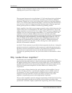
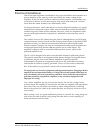
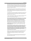
Figure 2: Amplifier rear panel controls and connections.
Warning: Be sure that the AC power is off prior to connecting or disconnecting any
signal wiring.
The input circuits of the Alesis amplifiers are electronically balanced. They may
be fed from either symmetrical (ÒbalancedÓ) or unbalanced sources. There are two
combination XLR/1/4Ó (6.3 mm) jacks provided, one for each channel, and a barrier
screw terminal strip for connecting bare wire or crimp terminals. See Figure 2.
The inputs are wired according to IEC standards:
Connection XLR Phone Jack
Audio Ground Pin 1 Sleeve
High (+) Pin 2 Tip
Low (Ð) Pin 3 Ring
Table 1: Input Wiring
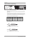
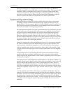
Figure 3. Balanced wiring of an XLR input connector.
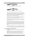
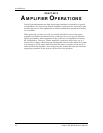
Figure 4. Unbalanced wiring of an XLR input connector.