


Installations
12 Matica 500/900 Reference Manual
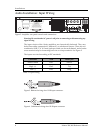
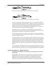
What we're doing here is compensation for the fact the Matica's B Channel is
normally internally inverted and then re-inverted at its output. This improves the
amplifier's ability to respond to high power low frequency signals better than
conventional amplifiers. The input and output wiring changes above "invert the
inversion" so the net effect is proper signal polarity and amplification with the
ability to operate both channel's outputs tied to a common speaker lead.
System Setup and Testing
Before applying power for the first time, double check the wiring to insure that
everything is firmly connected and that the proper signals are being fed to the
proper places. If a low frequency signal in a multi-amplified system is applied to a
high frequency transducer, the transducer can be damaged, and a loose connection
can cause noise which can damage any transducer.
Be certain that the amplifier front panel gain controls are set to minimum when the
system under test is first powered up. After the power is applied, slowly advance
each gain control to confirm that there are no driver-destroying hums or buzzes
presentÑif there are, turn the power off and locate the source of the difficulty.
When first applying program material to the system, it is also advisable to keep
the gain controls turned down to confirm, once again, that the wiring is correct. Once
the system wiring is determined to be correct, the gain controls can then be set to an
appropriate level for the system gain structure.
Setting the system gain is fairly straightforward, but if it is not properly adjusted,
the systemÕs distortion and noise characteristics may be less than optimum. The
input sensitivity of the Alesis amplifiers is 0.775Êvolts (0ÊdBu) for rated output
with the amplifier gain controls at maximum. If the signal at the amplifier input
is higher than this, the input gain controls must be turned down to avoid amplifier
clipping.
It is generally best to try to keep the gain of the source device balanced for best
signal-to-noise ratio consistent with distortion and to turn down the amplifier
inputs to reduce the amplification of noise artifacts originating prior to the signalÕs
reaching the amplifier.
The maximum level at the amplifierÕs input terminals is +22 dBu (10ÊVÊRMS). It is
possible that the output signal from the source may be too high and, thus, distorted
before it reaches the amplifier gain control, either because the source device is
clipping or the amplifier input stage is overloaded. In either case, no amount of
level control adjustment at the amplifier can remove this distortion, and the device
feeding the amplifier should have its gain lowered until the level is within proper
bounds.
It is also possible, particularly when using very efficient loudspeakers, that the
sound level from the loudspeakers may be too high when the amplifier is driven to
full output. In such cases, leaving the amplifier gain at maximum and turning down
the signal sourceÕs output level can result in audible noise products in the signal
coming from the source device or wiring. As above, keeping the source level as high
as possible and lowering the amplifier input gain will keep the noise level at a
minimum.