


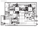
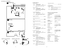
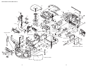
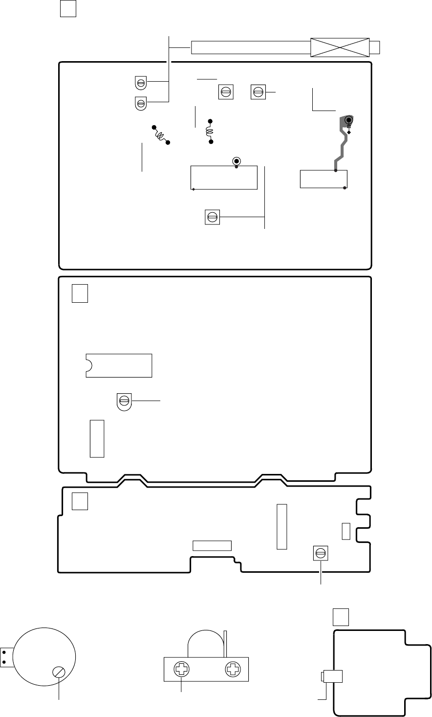
IC001
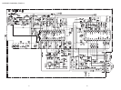
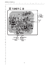
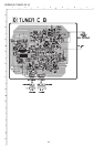
TUNER C.B
D
L004
L007
IC002
TP2(VT)
TP1(DET)
TC001
L003 (MW BAR ANT)
8
1
4
2
5
1
1
21
+
L006
16
L005
C039
!
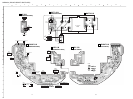
CASSETTE DECK HEAD
0
CASSETTE DECK MOTOR
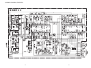
MAIN C.B
A
L801
IC801
CN201
CN801
@
PHONES
J251
H.P. C.B
E
!0
67
1
2
3
9
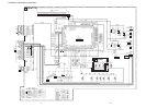
L051
3
TC051
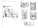
IC404
SFR430
#
CN401
CD C.B
B
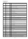
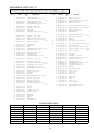
ELECTRICAL ADJUSTMENT
2827
< TUNER SECTION >
< FM SECTION >
Sensitivity: Less than 18dB (87.5MHz)
(THD 3%) Less than 18dB (98.0MHz)
Less than 18dB (108.0MHz)
Signal to Noise Ratio: More than 66dB (at 98.0MHz)
(Input 60dB) (EXCEPT U)
More than 58dB (at 98.0MHz)
(U)
Distortion: Less than 3% (at 98.0MHz)
(Input 60dB)
Intermediate frequency: 10.7MHz
Stereo separation: More than 20dB
< AM SECTION >
Sensitivity: Less than 48dB (at 600kHz)
(S/N 10dB) Less than 46dB (at 1000kHz)
Less than 44dB (at 1400kHz)
Distortion: Less than 3%
(Input 74dB)
Intermediate frequency: 450kHz
< LW SECTION >
Sensitivity: Less than 60dB (at 153kHz)
(S/N 10dB) Less than 56dB (at 198kHz)
Less than 52dB (at 288kHz)
Distortion: Less than 3%
(Input 80dB)
Intermediate frequency: 450kHz
< CASSETTE SECTION >
Tape speed: 3000Hz±60Hz
Wow & flutter: Less than 0.3% (JIS RMS)
Take-up torque: 30-60g-cm (FWD)
FF torque: 55-140g-cm
Rew torque: 55-140g-cm
S/N ratio: More than 35dB
Distortion: Less than 3.0% (PB)
Noise (PB): Less than 1mV
(AC/DC, MIN)
Erasing Ratio (W/FILTER): More than 45dB
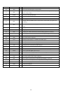
PRACTICAL SERVICE FIGURE
< TUNER SECTION >
1. FM VT Adjustment
Settings : • Test point : TP2 (VT)
• Adjustment location : L006
Method : Set to FM 108.0MHz and adjust L006 so that the
test point voltage becomes 6.0V ± 0.05V.
2. MW VT Adjustment
Settings : • Test point : TP2 (VT)
• Adjustment location : L004
Method : Set to MW 1000kHz (U), MW 999kHz (EZ,K)
and adjust L004 so that the test point voltage
becomes 3.75V ± 0.05V.
3. LW VT Adjustment <EZ,K>
Settings : • Test point : TP2 (VT)
• Adjustment location : L051
Method : Set to LW 288kHz and adjust L051 so that the
test point voltage becomes 4.5V ± 0.05V.
4. FM Tracking Adjustment
L005.........................................................................98.0MHz
5. MW Tracking Adjustment <U>
L003...........................................................................600kHz
TC001.......................................................................1400kHz
6. MW Tracking Adjustment <EZ,K>
L003...........................................................................603kHz
TC001.......................................................................1404kHz
7. LW Tracking Adjustment <EZ,K>
L003...........................................................................153kHz
TC051.........................................................................288kHz
8. AM IF Adjustment <U>
Settings : • Test point : TP1(DET)
• Adjustment location : L007
Method : Adjust L007 so that the output level at 1400kHz
becomes maximum.
9. AM IF Adjustment <EZ,K>
Settings : • Test point : TP1 (DET)
• Adjustment location : L007
Method : Adjust L007 so that the output level at 1404kHz
becomes maximum.
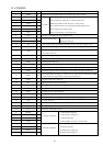
< DECK SECTION >
10. Tape Speed Adjustment
Settings : • Test tape : TTA–100
• Test point : J251 (PHONES jack)
• Adjustment location : SFR of deck motor
Method : Play back the test tape and adjust SFR so that
the frequency counter reads 3000Hz ± 30Hz.
11. Head Azimuth Adjustment
Settings : • Test tape : TTA–320
• Test point : J251 (PHONES jack)
• Adjustment location : Azimuth adjustment
screw
Method : Play back the 8kHz signal of the test tape and
adjust screw so that the output becomes
maximum.
12. Bias frequncy Adjustment
L801..................................................................85kHz±0.5kHz
< CD SECTION >
13. FE Balance Adjustment
Settings : • Test point : IC401 PIN58 (VR), IC401 PIN 20
(FE)
• Adjustment location : SFR430
Method : Playback the disc and adjust SFR430 so that the
test point voltage becomes 0V.