


To Video Switcher
***
To Video Switcher
***
3
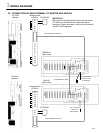
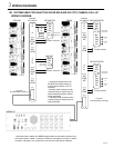
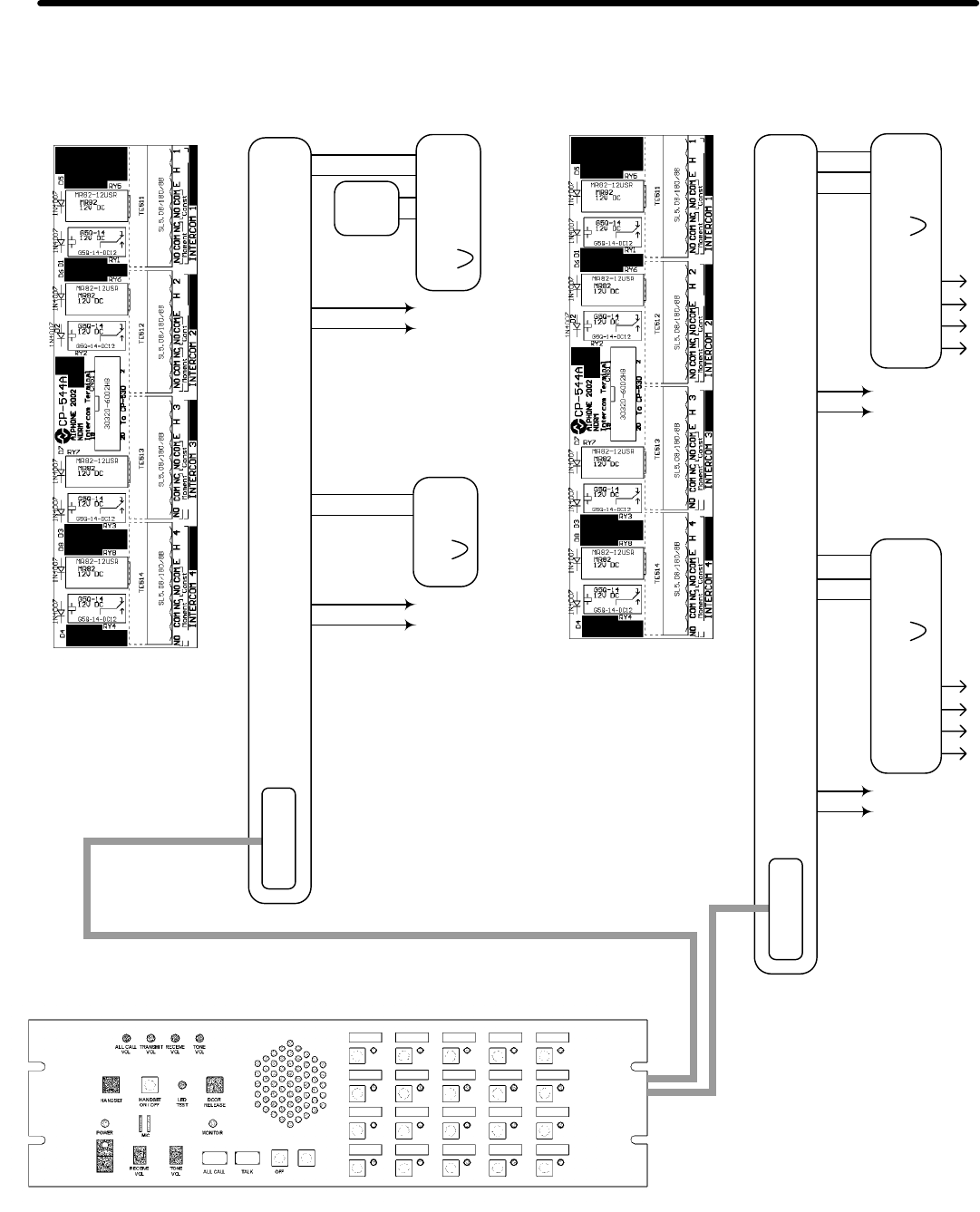
WIRING DIAGRAMS
3B. SYSTEM USED FOR SELECTIVE DOOR RELEASE OR CCTV CAMERA CALL-UP
WIRING DIAGRAM:
CP544
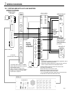
* Yellow and Orange wires from
NE-NVP-RA connect directly to
master board (CP543) "H" & "S"
terminals.
**Normally Open contacts remain
closed as long as master has sub
station selected and door release
button depressed.
***Normally Open contacts remain
closed as long as master has sub
station selected.
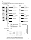
NDRM-20
* Numbered ribbon cables from NDRM master determine sub station placement on
the master console. Cable 1 connects to CP544 of sub stations 1 through 4, cable 2
for station 5 through 8, etc. Connection is the same for NDA add-on selectors.
5
E
H
NO
COM
NC
NO
COM
6
E
H
NO
COM
NC
NO
COM
Intercom
CP-544A #2
CN51
NE-NVP-2DC/B
To strike and power
To strike and power
CP-544A
NE-NVP-RA
Red
Blk
Yel
Org
1
E
H
NO
COM
NC
NO
COM
2
E
H
NO
COM
NC
NO
COM
Intercom
CP-544A #1
CN51
Pg. 5
Contact
#1
Contact
#2
Red
Blk
Wht
Blu
Org
Org
Yel
Yel
Grn
Grn
Leave green
jumper intact
NE-NVP-2DC/B
Contact
#1
Contact
#2
Red
Blk
Wht
Blu
Org
Org
Yel
Yel
Grn
Grn
Leave green
jumper intact
To CP-530
(Included Ribbon Cable #2)
To CP-530
(Included Ribbon Cable #1)
NE-NVP
Red
Blk
Grn
Grn
Leave green
jumper intact
Grn
Grn
Leave green
jumper intact
S
H
Mother
Board
CP-543A*
Moment
Const
Moment
Const
Moment
Const
Moment
Const
**
**