


To Video switcher
(Maintained Contact)
To Video switcher
(Maintained Contact)
To Video switcher
(Maintained Contact)
Pg. 6
3
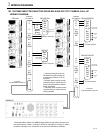
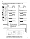
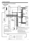
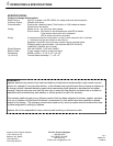
WIRING DIAGRAMS
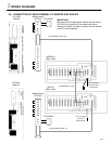
3C. SYSTEM WITH BOTH DOOR RELEASE AND CCTV CAMERA CALL-UP
WIRING DIAGRAM:
To CP 530
(Included Ribbon Cable #1)
NOTES:
1. "CONST" Contact on CP544 will be
closed as long as master has sub
station selected.
2. "MOMENT" Contacts connected
directly to CP544 remain closed as
long as master has sub station
selected and door release button
pressed.
* Numbered ribbon cables from NDRM master determine sub station placement on
the master console. Cable 1 connects to CP544 of sub stations 1 through 4, cable 2
for station 5 through 8, et cetera. Connection is the same for NDA add-on selectors.
CP-544A
To strike and power
(Momentary Contact)
1
E
H
NO
COM
NC
NO
COM
2
E
H
NO
COM
NC
NO
COM
Intercom
CP-544A #1
CN51
5
E
H
NO
COM
NC
NO
COM
6
E
H
NO
COM
NC
NO
COM
Intercom
CP-544A #2
CN51
NE-NVP
Red
Blk
Grn
Grn
Leave green
jumper intact
NE-NVP
Red
Blk
Grn
Grn
Leave green
jumper intact
NE-NVP
Red
Blk
Grn
Grn
Leave green
jumper intact
NE-NVP
Red
Blk
Grn
Grn
Leave green
jumper intact
To strike and power
(Momentary Contact)
To strike and power
(Momentary Contact)
To strike and power
(Momentary Contact)
To CP 530
(Included Ribbon Cable #2)
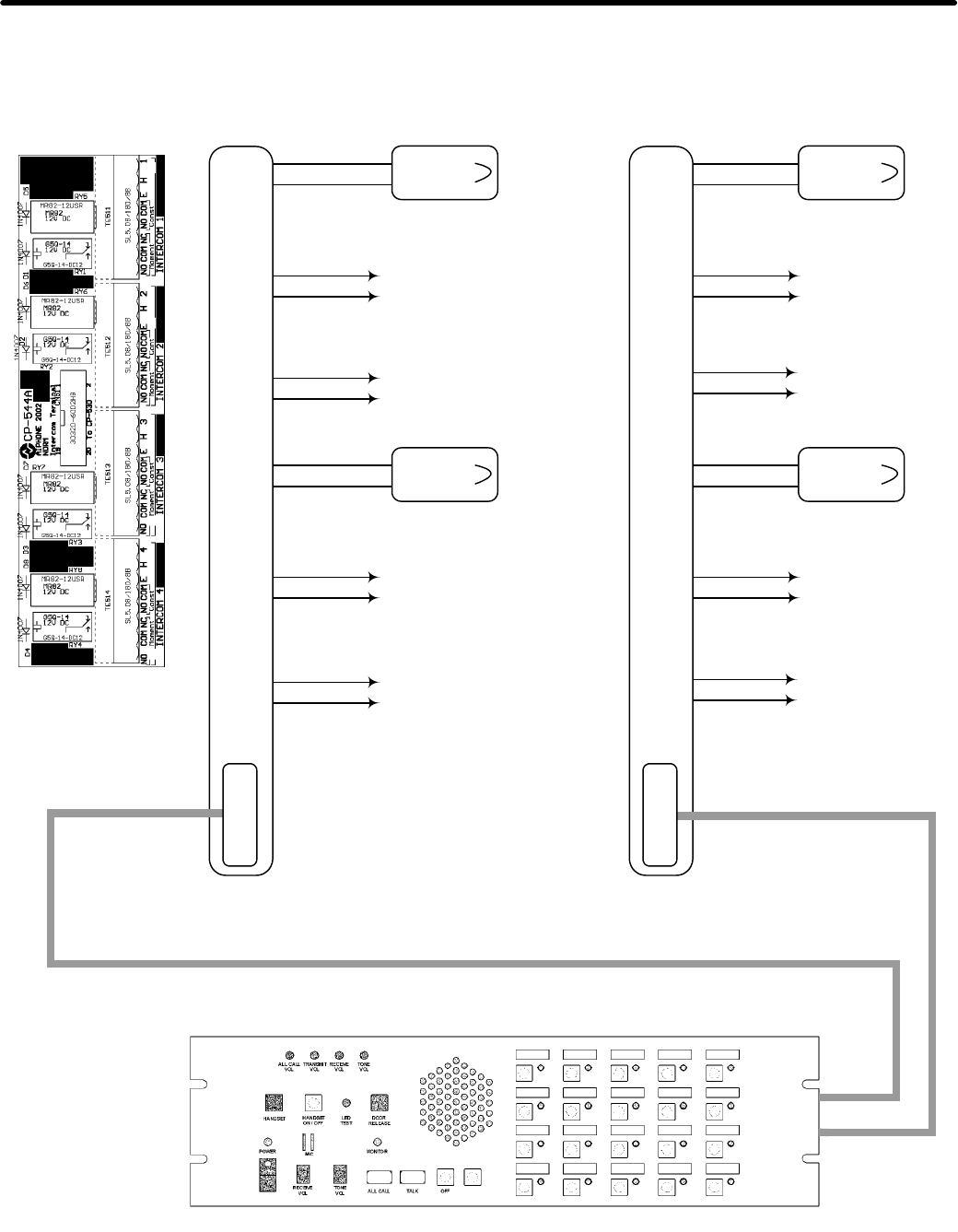
NDRM-20
Moment
Moment
To Video switcher
(Maintained Contact)
Const
Const
Const
Moment
Const
Moment