


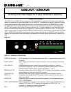
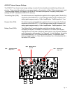
CT1
AT2
AT1
DT2
DT1
CR2
CR1
AR2
AR1
DR2
DR1
VID
SYN
RX C/E
TX C/L
DIAG
PWR
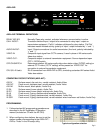
VIDEO
OPTICAL
TX
RX
CT2
1
3
5
1
4
1
3
5
DATAC.C.AUDIO
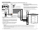
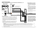
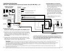
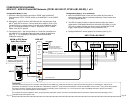
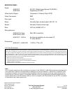
CONFIGURATION DIAGRAM:
AXW-AVT / AXW-AVR with Meridian Technology Fiber (ST/SR-1W1A2C/1A2C-XS), 1 of 2
CCTV Camera
75 Ohm, 1V Peak-to-peak
(Independently powered)
Normally Closed input for remote activation
(i.e. motion sensor, loop detector, etc.)
Normally Open contact for remote device activation
(i.e. video switcher, DVR, etc.)
Configuration Notes (1 of 2):
1. AX-series video door station connects to ‘DOOR’ input of AXW-AVT.
Ensure that the “CCTV / DOOR’ switch on the AXW-AVT is in the ‘DOOR’
position.
*2. Alternatively, an IE/IF-series or AX-DM audio door may be used, along
with 3
rd
party CCTV camera. Connect audio door station to ‘Door’ input
(following the wiring method shown in the AX-series installation manual,
pg. 12). Connect the camera to ‘Video In’ and put the ‘CCTV / DOOR’
switch in the ‘CCTV’ position.
3. Connect the Call In / Call Out and Audio In / Audio Out connections on
the AXW-AVT to the Meridian fiber transmitter module (as detailed at
right, Fig. 1). For complete pin definitions, consult the Meridian
installation document.
Pg. 3
AXW-AVT
24V
+
-
RELAY
NO
NO
SENSOR
NC
NC
CALL IN
+
-
CALL OUT
+
-
AUDIO IN
+
-
AUDIO OUT
+
-
DOOR
VIDEO IN
VIDEO OUT
AX-DV
AX-DM or IE/IF-Series
Audio Door Station
CAT-5e
Coax
*
Coaxial Video Cable
Optic Fiber
(to SR-1W1A2C/1A2C-XS, Pg. 5)
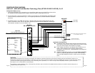
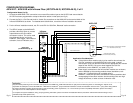
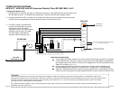
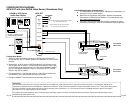
Connection details from
AXW-AVT to ST-1W1A2C/1A2C-XS
‘Audio’ Connector Detail:
Pin 1 Audio Out -
Pin 2 Audio Out +
Pin 3 Audio In -
Pin 4 Audio In +
‘C.C.’ Connector Detail:
Pin 1 Call Out -
Pin 2 Call Out +
Pin 3 Call In +
Pin 4 Call In -
‘DATA’ Connector Detail:
Pin 1 & 2 Optional Door
release contact
output
+
-
PS-2420UL
Pg. 4
Meridian
ST-1W1A2C/1A2C-XS
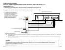
Configuration Notes (1 of 2, continued):
4. When the SENSOR input is used, the door station will be turned on
whenever the sensor device is activated (Normally Closed contact from
3
rd
party supplied device).
5. The RELAY output provides an optional Normally Open dry contact
output which is activated whenever the AX-series door station is in use.
This can be used to activate any device local to the AXW-AVT (DVR
trigger, video switcher activation, local call indication, etc.).
6. Configure AXW-AVT internal jumpers as necessary (see Pg. 21).
Fig. 1
Please Note:
Only information pertaining to the connection and operation of the AXW-AVT / AXW-AVR and listed 3
rd
party devices interfacing with it are included here. Aiphone is not
responsible for attempts to connect the AXW-AVT / AXW-AVR to untested 3
rd
party transmission hardware. Consult the installation manual for the 3
rd
party device being utilized
for further information regarding physical mounting, base functionality, power requirements, etc. For the most up-to-date compatibility information, please consult http://
www.aiphone.com or contact Aiphone Technical Support.
For complete AX system installation, wiring, and programming information, please consult the AX Installation Manual (included on CD with AX Central Exchange Unit, or
available at http://www.aiphone.com).
To Door
Release