


CTH3-SERIES INSTALLATION, OPERATION AND SERVICE MANUAL
44 of 71
10.4 Heat Demand Control Wiring
The heater input can be controlled by any one of the
following heat demand control devices (control
dev ices are wired to central heaters only):
10.4.1 Zone Sensor
The zone sensor (P/N 10081530) offers automatic
control of heater input. Heater(s) modulates based
on difference between sensed air temperature and
the temperature setpoint. Heater modulation in
response to air temperature changes is immediate.
Setpoint is adjusted with the slide bar adjustment at
the bottom of the sensor. ON/OFF switch (used to
disable heater operation or reset heater from lockout)
is located on the side of the sensor. See Page 39,
Figure 22 for wiring details.
10.4.2 Thermostat
A thermostat offers automatic control of heater input.
The heater control is designed for use with a
standard 2-wire or 4-wire low voltage electronic
thermostat (not for use with thermostats that have a
heat anticipator). Typical wiring connects the R and
W wires to the heater control and does not connect
the Y (cooling) and G (fan) wires to the heater
control.
The heater can be used with thermostat, 24V (p/n
90425100) if set to 5 cycles per ho
ur. Any other
electronic thermostat without heat anticipator can be
used if set to 5 or 6 cycles per hour.
On the control, the T24 and T25 (R and W) terminals
supply 24 V to power an electronic thermostat. See
Page 44, Figure 26 for wiring details. Consult the
factory for other thermostat wiring configurations.
Heater(s) modulates based on heater and thermostat
cycle timing, history and desired setpoint by using a
pre-programmed algorithm. When using thermostat
control, heater modulation response to rapid air
temperature change is not immediate. Thermostat
control is not recommended for use in areas with
frequent or high air changes.
It is important to note that during normal operation,
heater cycle continues beyond meeting thermostat
setpoint.
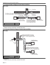
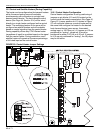
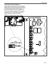
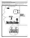
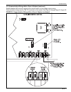
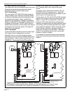
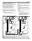
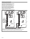
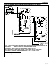
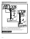
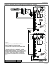
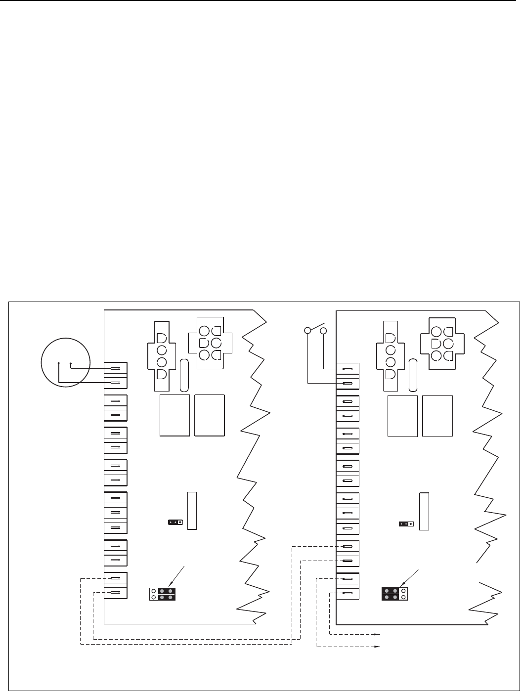
FIGURE 26: Thermostat Control Wiring Diagram
*OPTIONAL
SWITCH
SATELLITE HEATER CONTROL
J10 JUMPER POSITION
SHOWS "SATELLITE" DESIGNATION.
MODULATION CONTROL WIRING
TO ADDITIONAL SATELLITE
HEATER CONTROL TERMINALS
T28 AND T29.
MODULATION CONTROL WIRING
TO SATELLITE HEATERS
CENTRAL HEATER CONTROL
T31
T29
T19
T18
T16
T14
T27
T25
T30
T28
T17
T15
T13
T26
T24
T31
T29
T19
T18
T16
T14
T27
T25
T30
T28
T17
T15
T13
T26
T24
RW
T
J10
W
R
-+
-
+
-+
OUT
RATE
FIRING
IN
RATE
FIRING
EXT. POT
GND
WIPER
HIGH
GND
BAR
SLIDE
GND
THERMISTOR
INPUT
ANALOG
THERMOSTAT
J10
W
R
-+
-
+
-+
OUT
RATE
FIRING
IN
RATE
FIRING
EXT. POT
GND
WIPER
HIGH
GND
BAR
SLIDE
GND
THERMISTOR
INPUT
ANALOG
THERMOSTAT
J10 JUMPER POSITION
SHOWS "CENTRAL"
DESIGNATION AND
"THERMOSTAT"
CONTROL METHOD.
* Separate on/off switch is optional for "satellite" heaters (install at user level).
On/Off switch is used to disable heater operation or reset a heater that is in "lockout" mode.
If on/off switch is not desired, leave jumper wire between R and W terminals in place.